Mutual capacitance touch sensing device

a capacitance sensing and capacitance technology, applied in the direction of instruments, transmission systems, computing, etc., can solve the problems of large number of i/o contacts, large stacking of operational components, and limited size of portable electronic devices

Inactive Publication Date: 2008-01-10
APPLE INC
View PDF99 Cites 155 Cited by
  • Summary
  • Abstract
  • Description
  • Claims
  • Application Information

AI Technical Summary

Benefits of technology

[0010] The invention relates, in one embodiment, to a touch sensing device. The touch sensing device includes one or more multifunctional nodes each of which represents a single touch pixel. Each multifunctional node includes a touch sensor with one or more integrated I/O mechanisms. The touch sensor and integrated I/O mechanisms share the same communication lines and I/O pins of a controller during operation of the touch sensing device.
[0011] The invention relates, in another embodiment, to an I/O device for use in a user interface of an electronic device. The I/O device includes

Problems solved by technology

In most cases, the size of the portable electronic device is limited by the size of the operational components used therein.
For thin devices such as cell phones, PDAs and media players, stacking operational components on top of each other is limited and therefore the operational components may be placed side by side.
Large numbers of I/O contacts create design diffi

Method used


Image

  • Mutual capacitance touch sensing device
  • Mutual capacitance touch sensing device
  • Mutual capacitance touch sensing device

Examples


Embodiment Construction

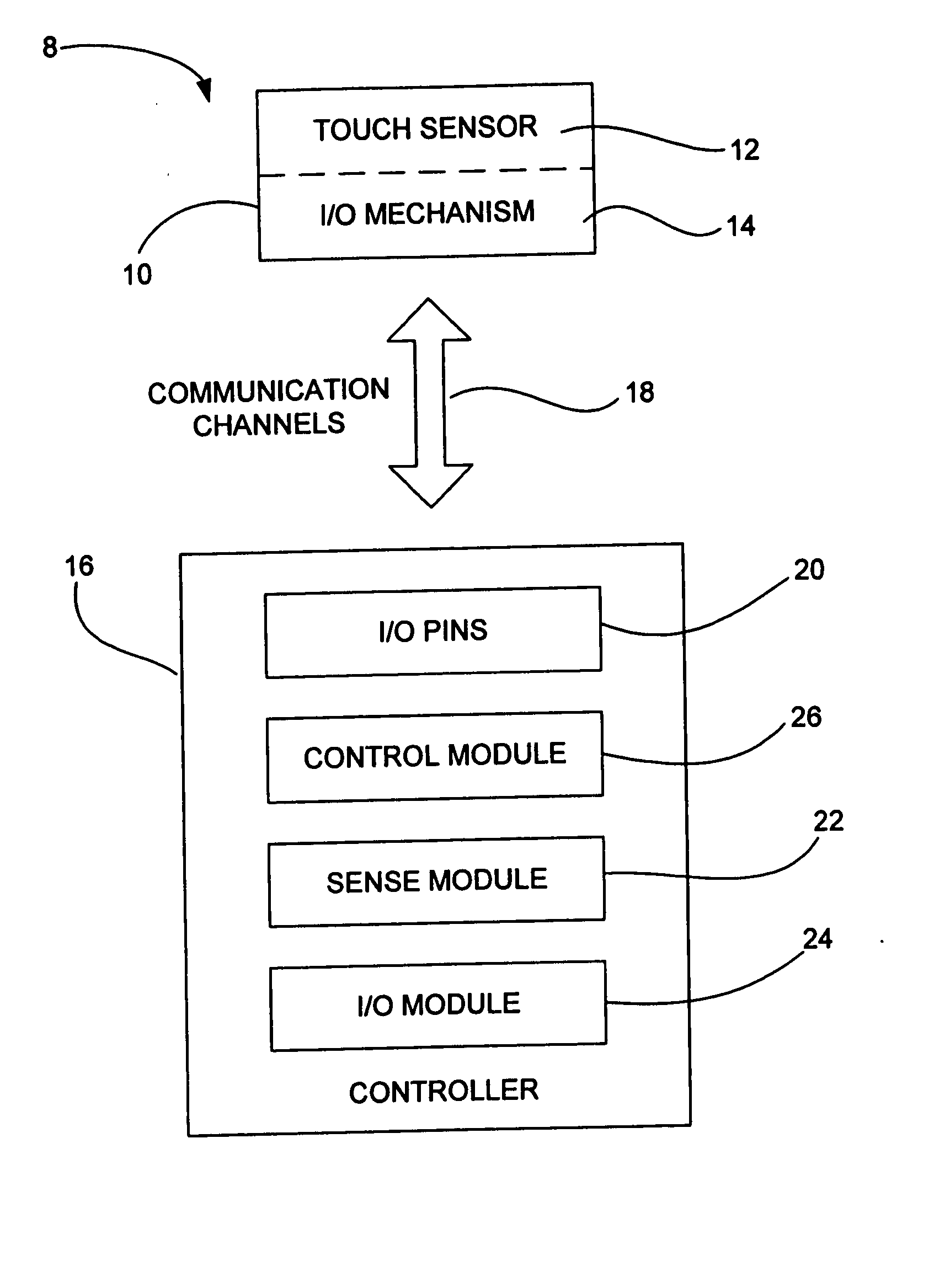
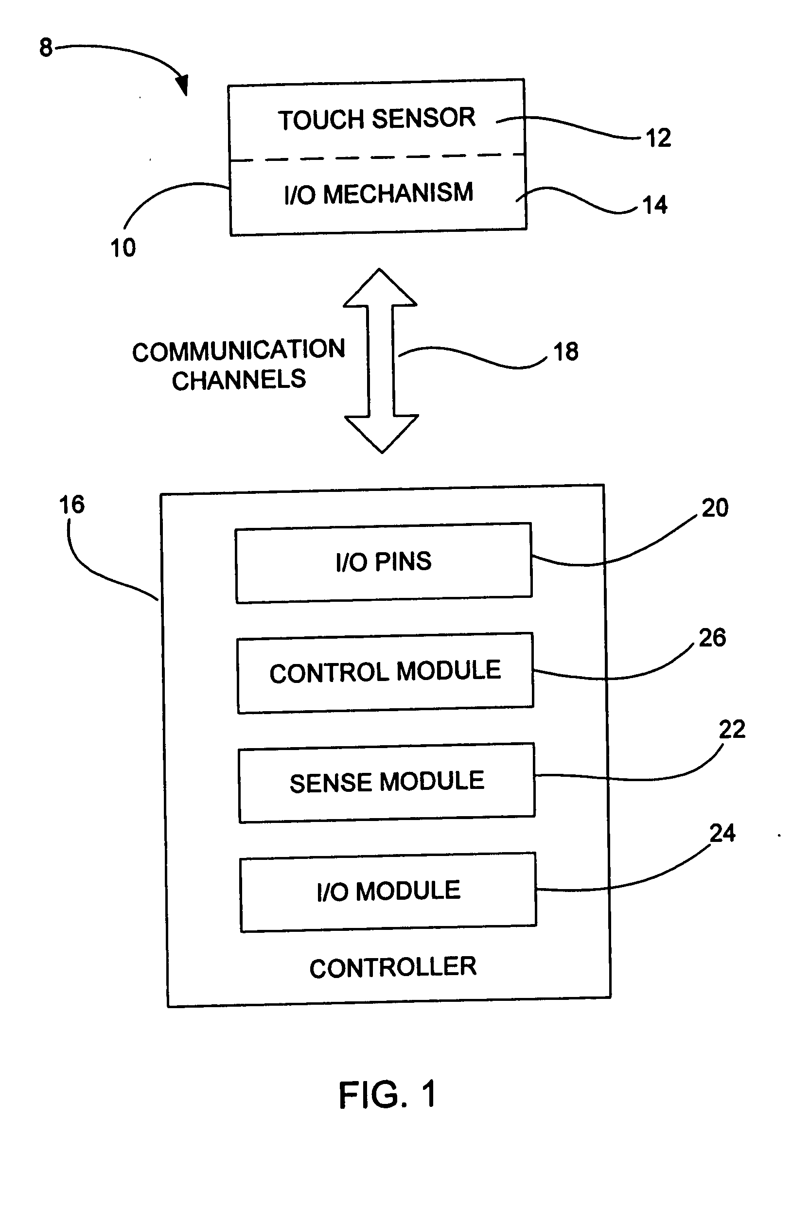
[0042] The user interface is believed to be one or the more important features of an electronic device since it deals directly with the user experience. It typically provides the form, feel and functionality of the device. If the user thinks the user interface is low grade, the user typically thinks the quality of the electronic device as a whole is also low grade. In contrast, if the user thinks the user interface is high grade, the user typically thinks the quality of the electronic device as a whole is also high grade. As such, designers have been making great efforts to improve the design (form, feel and functionality) of the user interface.

[0043] There exist today many styles of input devices for use in the user interface. The operations generally correspond to moving objects and making selections and entering data. By way of example, the input devices may include buttons, keys, dials, wheels, mice, trackballs, touch pads, joy sticks, touch screens and the like.

[0044] Touch d...


PUM


Abstract

A touch sensing device is disclosed. The touch sensing device includes one or more multifunctional nodes each of which represents a single touch pixel. Each multifunctional node includes a touch sensor with one or more integrated I/O mechanisms. The touch sensor and integrated I/O mechanisms share the same communication lines and I/O pins of a controller during operation of the touch sensing device.

Description

CROSS REFERENCE TO RELATED APPLICATIONS [0001] This application is related to the following applications, all of which are herein incorporated by reference: [0002] U.S. patent application Ser. No. 10 / 188,182, titled “TOUCH PAD FOR HANDHELD DEVICE,” filed Jul. 1, 2002; U.S. patent application Ser. No. 10 / 722,948, titled “TOUCH PAD FOR HANDHELD DEVICE,” filed Nov. 25, 2003; U.S. patent application Ser. No. 10 / 643,256, titled “MOVABLE TOUCH PAD WITH ADDED FUNCTIONALITY,” filed Aug. 18, 2003; U.S. patent application Ser. No. 10 / 840,862, titled “MULTIPOINT TOUCHSCREEN,” filed May 6, 2004; U.S. patent application Ser. No. 11 / 057,050, titled “DISPLAY ACTUATOR,” filed Feb. 11, 2005; U.S. patent application Ser. No. 11 / 115,539, titled “HAND HELD ELECTRONIC DEVICE WITH MULTIPLE TOUCH SENSING DEVICES,” filed Apr. 26, 2005; and U.S. patent application Ser. No. 11,482,286, titled “MUTUAL CAPACITANCE TOUCH SENSING DEVICE,” filed Jul. 6, 2006, and U.S. patent application Ser. No. 11 / 483,008, title...

Claims


Application Information

Patent Timeline
IPC IPC(8): G08C21/00G06F3/044
CPCG06F3/03547H04M2250/22G06F3/044G06F3/0446G06F3/0447
Inventor HOTELLING, STEVE P.
Owner APPLE INC
Why Eureka
Try Eureka