Apparatus and method for positioning a module on an object

a technology of a module and an object, applied in the field of apparatus and methods for positioning can solve the problems of difficult to solve, unsolved problems in the use of such apparatuses, and prior approaches suggested for mounting a module on an object include significant limitations and problems, and achieve the effects of convenient use and practice, rapid adjustment and relocation, and easy installation

Inactive Publication Date: 2008-01-17
UNIRAC INC
View PDF99 Cites 112 Cited by
  • Summary
  • Abstract
  • Description
  • Claims
  • Application Information

AI Technical Summary

Benefits of technology

[0018] The advantages and objects of such an apparatus and method for positioning a module on an object include additional advantages in connection with mounting, attaching, adjusting, and detaching a rail to or from one or more objects and modules, and for removing the one or more modules from a surface and object in a safe, reliable, yet rapid manner. At least one advantage of the present invention is an apparatus, and a method of installing the apparatus, is that it allows installation both top down and bottom up using a rail system that includes a triple track rail in combination with the connector bracket of the present invention. The present invention also significantly reduces the number and variety of hardware parts and components needed to assemble the apparatus and connect the apparatus to an object other than fasteners. In the vast majority of installations of a module, the connector bracket of the present invention is the only additional item of hardware needed to interconnect a rail, a module, a keeper, grid and object. In addition, the system provided by the present invention provides universal hardware, permitting installation of a module on a surface and object either in any direction or configuration.
[0019] The present invention also allows assembly of photovoltaic modules of any size or shape on a variety of surfaces. The unique triple track rail of the present invention, in combination with the novel connector bracket of the present invention, permit rapid installation as well as rapid adjustments and relocation of a module and a rail system. Equally significant, the present invention is easy to use and to practice, and is cost effective for the intended purposes.
[0020] The advantages, objects, and features of the present invention will become apparent to those skilled in the art when read in conjunction with the accompanying following description, drawing figures, and appended claims. It is clear, however, from the foregoing that the claimed subject matter as a whole, including the structure of the apparatus, and the cooperation of the elements of the apparatus, as well as the method for installing and using the apparatus, combine to result in a number of unexpected advantages and utilities of the present invention.
[0021] The foregoing has outlined broadly the more important features of the invention to better understand the detailed description which follows, and to better understand the contribution of the present invention to the art. Before explaining at least one embodiment of the invention in detail, it is to be understood that the invention is not limited in application to the details of construction, and to the arrangements of the components, provided in the following description or drawing figures. The invention is capable of other embodiments, and of being practiced and carried out in various ways. Also, the phraseology and terminology employed in this disclosure are for purpose of description, and should not be regarded as limiting.
[0022] As used in this document, the term “device” is not limited to the photovoltaic environment. For example, but not by way of limitation, the term includes any device capable of generating power, but may also be a device capable of holding liquids, gases or admixtures of solids. A device may be mounted on a surface which may include the roof or wall of a building, a pole, or any other surface. The shape of the device is not material to the present invention, and may be rectangular, circular, or any other shape or configuration.

Problems solved by technology

Mounting devices to objects that are, or maybe, exposed to unpredictable and varying force vectors caused by wind, rain, and other elements of weather present technical problems often difficult to solve.
A long standing and unsolved challenge in the solar energy industry, for example, has been resolving how best to mount panels, modules and arrays of photovoltaic devices (collectively, “module” or “modules”) on surfaces not only securely and safely, but also quickly.
The obverse problem also is significant to the industry, namely safely removing or reconfiguring a module that has been installed on a surface.
Solar energy, however, due to technological improvements in the manner of collecting the potential energy, has become increasingly attractive as an energy source: it is inexhaustible in supply, and non-polluting, both in stark contrast to fossil-fuel sources like coal, oil, and natural gas.
The construction, installation, and use of such apparatus present a number of unsolved problems.
Prior approaches suggested for mounting a module on an object include significant limitations and problems.
A serious challenge to providing a useful apparatus and method for mounting a module on a surface arises from the variety of sizes and shapes of the modules, as well as the varying number of modules that might be required in a given situation.
Another challenge that earlier suggestions did not overcome is the variety of surfaces on which modules may or must be mounted, including roofs, tops and sides of poles, the ground, and other locations.
Many earlier suggestions for mounting panels, modules and arrays of photovoltaic devices on surfaces are cumbersome, unsafe, and not easily assembled or reconfigured.
Also, none of the solutions provided an apparatus, and method for installing the apparatus, that would be universal.
Significantly, none of the currently available apparatus for mounting photovoltaic modules to a surface allow installation both top down and bottom up using the same rail system.
Another limitation of current approaches for mounting photovoltaic modules to a surface is the excessive number and variety of hardware parts and components that are required to assemble a frame or rail system.
Still another unresolved problem arises from the varying shapes, sizes and configurations of modules.
Still another limitation of present apparatus for assembling and mounting modules on surfaces is the absence of a system and apparatus that permits easily adjusting and readjusting of the location on a rail on which the module may be positioned.

Method used


Image

  • Apparatus and method for positioning a module on an object
  • Apparatus and method for positioning a module on an object
  • Apparatus and method for positioning a module on an object

Examples


Embodiment Construction

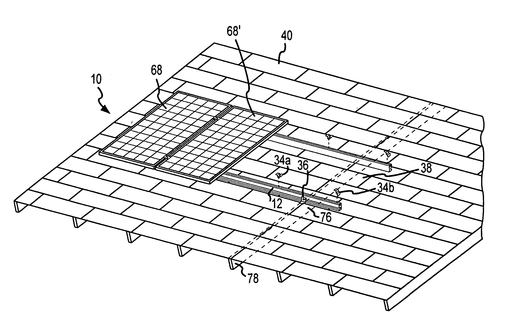
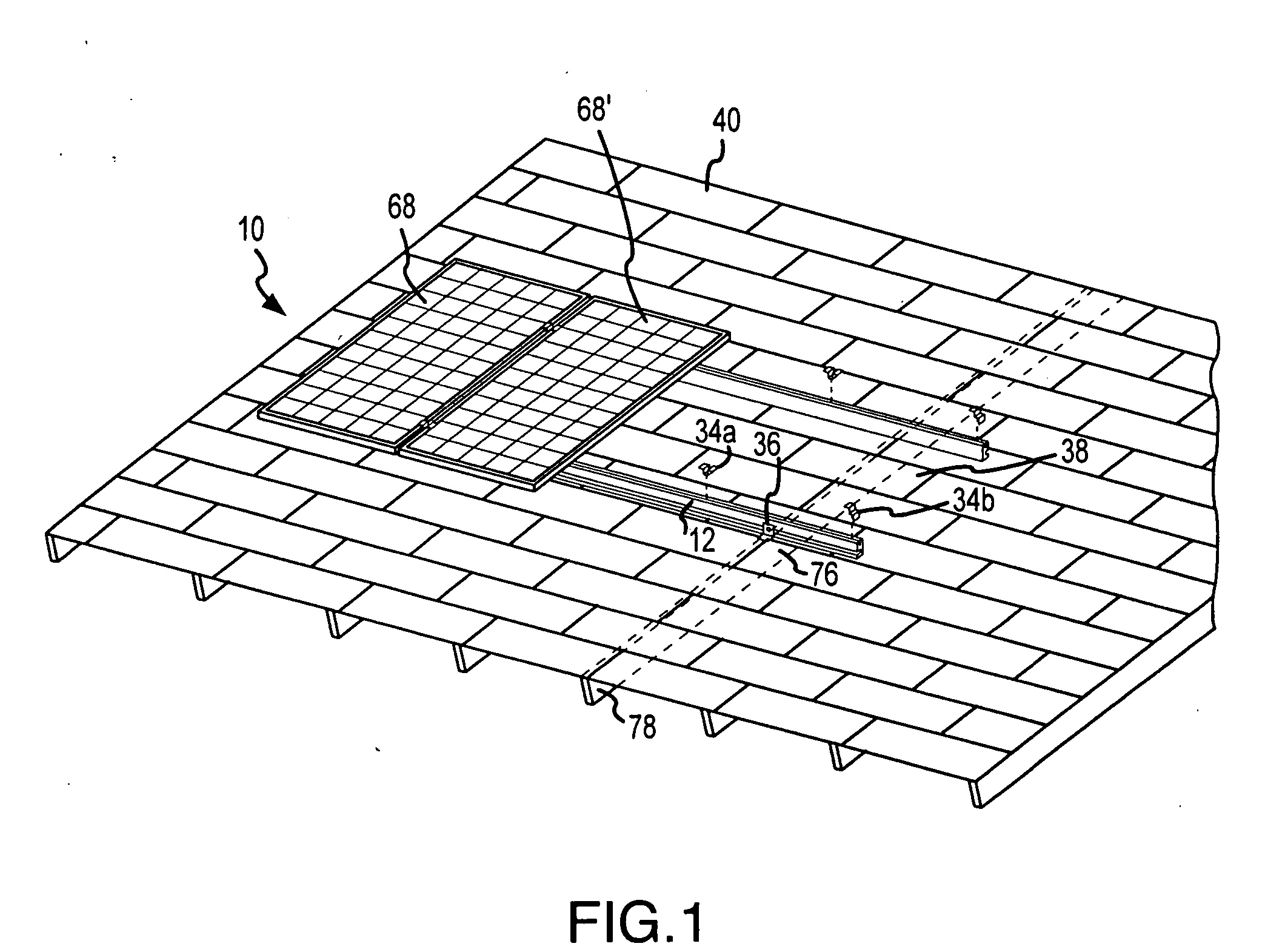
[0042] Briefly, the present invention provides a system for removably and adjustably mounting a device on a surface. The invention includes one or more dual track rails and one or more unique clamps that may be interconnected to a footing grid.

[0043]FIG. 1 illustrates the system for removably and adjustably mounting a device on a surface in an operative environment. As shown, the present invention is an apparatus for removably and adjustably mounting one or more photovoltaic modules on a surface such as a roof. Referring initially to FIG. 1, the system for removably and adjustably mounting a device on a surface is shown and generally designated 10. The system for removably and adjustably mounting a device on a surface 10, according to the present invention, includes at least one rail 12. In a preferred embodiment of the present invention, at least one rail 12 is formed of extruded aluminum, but the material used is not a material consideration to the present invention. As shown per...


PUM


Abstract

A system for removably and adjustably mounting a device on an object is provided. The system for removably and adjustably mounting a device on an object, according to the present invention, includes an apparatus and method useful for removably and adjustably mounting one or more photovoltaic modules on an object such as a pole or roof, and includes one or more triple track rails. Also included are one or more connector brackets that are demountably attachable to the one or more triple track rails and to the object.

Description

CROSS-REFERENCE TO RELATED APPLICATION(S) [0001] Applicant claims priority to this continuation nonprovisional patent application based on the copending nonprovisional United States patent application filed by the same applicant and sole inventor named in this application filed in the United States Patent and Trademark Office on Apr. 4, 2002, application Ser. No. 10 / 116,384, which is a continuation-in-part of the application filed by the same applicant and sole inventor named in this application filed on Jul. 20, 2001, application Ser. No. 09 / 910,655.FIELD OF THE INVENTION [0002] The present invention pertains generally to an apparatus and method for removably and adjustably mounting a device on a surface. More particularly, the new and useful invention claimed in this document pertains to an system for securely, safely, yet quickly mounting one or more photovoltaic devices onto a surface including, but not limited to, a roof. The present invention is particularly, but not exclusive...

Claims


Application Information

Patent Timeline
Patent Type & Authority Applications(United States)
IPC IPC(8): E04D13/18F24J2/52
CPCF24J2/5205F24J2/5247F24J2/5258F24J2/526H01L31/0482H02S20/00Y02B10/20Y02E10/47Y02E10/50H02S20/23Y02B10/12F24S25/33F24S25/613F24S25/636F24S25/65F24S2025/6008F24S2025/801F24S2025/807Y02B10/10
Inventor LIEBENDORFER, JOHN E.
Owner UNIRAC INC
Why Eureka
Try Eureka