Al technical title is built by PatSnap Al team. It summarizes the technical point description of the patent document.
a hammermill and hammer technology, applied in the field of impact grinders and hammermills, can solve the problems of material short circuit, material being reduced, art grates or screens being restricted and plugged,
Inactive Publication Date: 2008-01-17
ELLIOTT JAMES C
View PDF10 Cites 4 Cited by
Summary
Abstract
Description
Claims
Application Information
AI Technical Summary
This helps you quickly interpret patents by identifying the three key elements:
Problems solved by technology
Method used
Benefits of technology
[0009] The present invention provides an improved hammermill which overcomes some of the design defects of the known hammermills. The hammermill of the present invention comprises a housing, a rotor assembly disposed within the housing for rotation about a longitudinal axis of the housing, a plurality of hammers coupled to the rotor assembly, and an attrition plate assembly secured to a sidewall of the housing. The housing has an inlet end defining an inlet opening, a discharge end, with the longitudinal axis of the housing extending therebetween. The sidewall of the housing extends between the inlet end and the discharge end. The housing further defines a primary reduction chamber, an adjoining secondary reduction chamber, and, if used, a tertiary reduction chamber. In one embodiment, the sidewall of the housing and the inlet opening define a partially enclosed work space in the primary reduction chamber, and, in the secondary reduction chamber, the sidewall of the housing defines an enclosed work space. If used, the sidewall of the housing and the inlet opening define a partially enclosed work space in the tertiary r
Problems solved by technology
Unfortunately, in prior art hammermills, material can “short circuit” or by-pass the hammers by being forced through the apertures in the grates or screens before being thoroughly processed or sized.
Furthermore, the prior art grates or screens can become restricted and plugged with the materials being reduced, which, in turn, reduces the throughput and efficiency of the hammermill.
In particular, wood that has a “stringy bark,” such as poplar, hickory, and eucalyptus, is very problematic for the grates and thus
Method used
Image
Click on the blue label to locate the original text in one second.
Reading with bidirectional positioning of images and text.
Examples
Embodiment Construction
[0037] The present invention is more particularly described in the following exemplary embodiments that are intended as illustrative only since numerous modifications and variations therein will be apparent to those skilled in the art. As used herein, “a,”“an,” or “the” can mean one or more, depending upon the context in which it is used. The preferred embodiments are now described with reference to the figures, in which like reference characters indicate like parts throughout the several views.
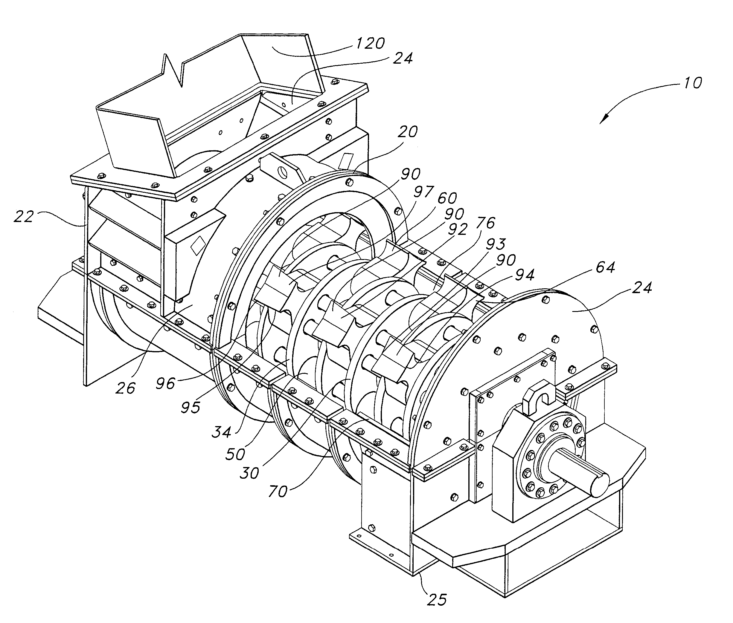
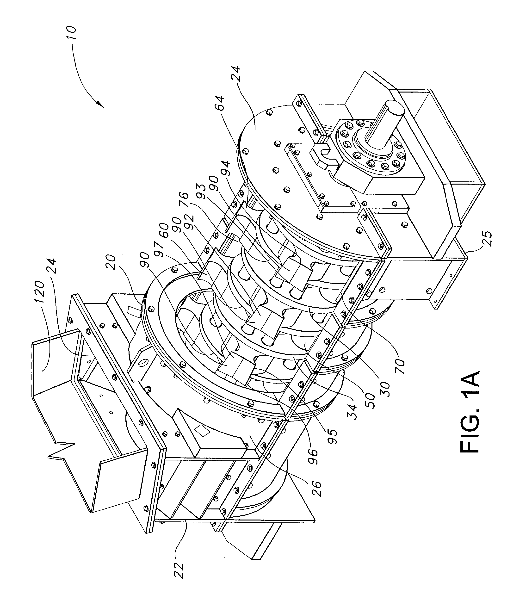
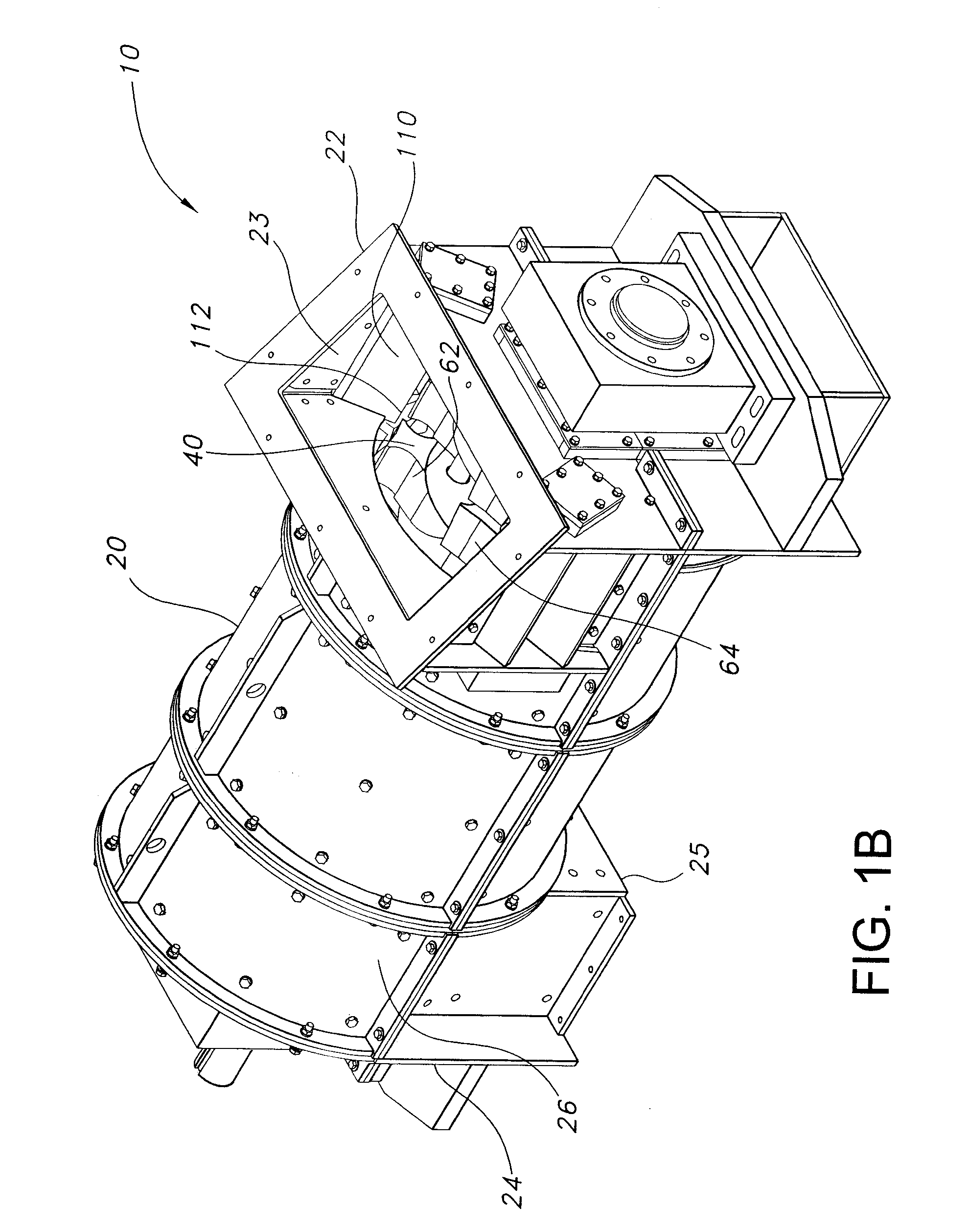
[0038] The present invention comprises a hammermill 10 as shown generally in FIGS. 1A-12B and 20. The hammermill 10 of the present invention is adapted for reducing wood or similar fibrous materials (i.e., for use as a hammermill 10 which is typically referred to as a hog or a wood / bark hog), but one skilled in the art will appreciate that the design features of the present invention are applicable to comminute other types of friable materials, such as coal, minerals, agricultural products, ...
PUM
Abstract
A hammermill having a housing, a rotor assembly, a plurality of hammers, and an attrition plate assembly is provided to reduce oversized particulate material to a desired size. The housing defines an enclosed work space. The rotor assembly is disposed within the housing for rotation about a longitudinal axis of the housing. The plurality of hammers is coupled to the rotor assembly and is disposed within the enclosed work space. Each hammer having an impact end, a connection portion adapted to couple to a portion of the rotor assembly, and a shank portion extending between the impact end and the connection portion.
Description
[0001] This application is a Divisional of U.S. Utility patent application Ser. No. 11 / 281,628, entitled “A Hammer For A Hammermill,” filed Nov. 17, 2005, which claims priority to and the benefit of U.S. Utility patent application Ser. No. 10 / 690,937, entitled “A Hammermill,” filed Oct. 22, 2003, which claims priority to and the benefit of U.S. Provisional Application No. 60 / 420,256, entitled “A Hammermill,” filed on Oct. 22, 2002, and is a continuation-in-part of issued U.S. Pat. No. 6,926,215, entitled “A Hammermill,” filed May 17, 2002 and issued Aug. 9, 2005, which claims priority to the U.S. Provisional Application No. 60 / 292,213, entitled “Hammermill,” filed May 17, 2001, all of which are incorporated in their entirety in this document by reference.BACKGROUND OF THE INVENTION [0002] 1. Field of the Invention [0003] The present invention relates to impact grinders, hammermills, or the like, and particularly to a screenless hammermill that can be used to reduce the size of mater...
Claims
Application Information
Patent Timeline
Application Date:The date an application was filed.
Publication Date:The date a patent or application was officially published.
First Publication Date:The earliest publication date of a patent with the same application number.
Issue Date:Publication date of the patent grant document.
PCT Entry Date:The Entry date of PCT National Phase.
Estimated Expiry Date:The statutory expiry date of a patent right according to the Patent Law, and it is the longest term of protection that the patent right can achieve without the termination of the patent right due to other reasons(Term extension factor has been taken into account ).
Invalid Date:Actual expiry date is based on effective date or publication date of legal transaction data of invalid patent.