Eureka AIR delivers breakthrough ideas for toughest innovation challenges, trusted by R&D personnel around the world.

Pressure energized radial seal

Active Publication Date: 2008-01-24
HYDRIL USA DISTRIBUTION LLC
View PDF19 Cites 12 Cited by
  • Summary
  • Abstract
  • Description
  • Claims
  • Application Information

AI Technical Summary

Benefits of technology

[0017]Other aspects and advantages of the invention will be apparent from the following description and the appended claims.

Problems solved by technology

If the kick is allowed to reach the surface, drilling fluid, well tools, and other drilling structures may be blown out of the wellbore.
Such “blowouts” may result in catastrophic destruction of the drilling equipment (including, for example, the drilling rig) and substantial injury or death of rig personnel.
Furthermore, face seals may be more susceptible to a loss of seal integrity.
For example, when sealing across imperfections and defects (e.g., scratches, gouges, abrasions) in seal surfaces, face seals may be more susceptible to have leak across the seal.
A concern with these types of sealing assemblies, though, may relate to the inability to seal at low pressures.

Method used


Image

  • Pressure energized radial seal
  • Pressure energized radial seal
  • Pressure energized radial seal

Examples


Embodiment Construction

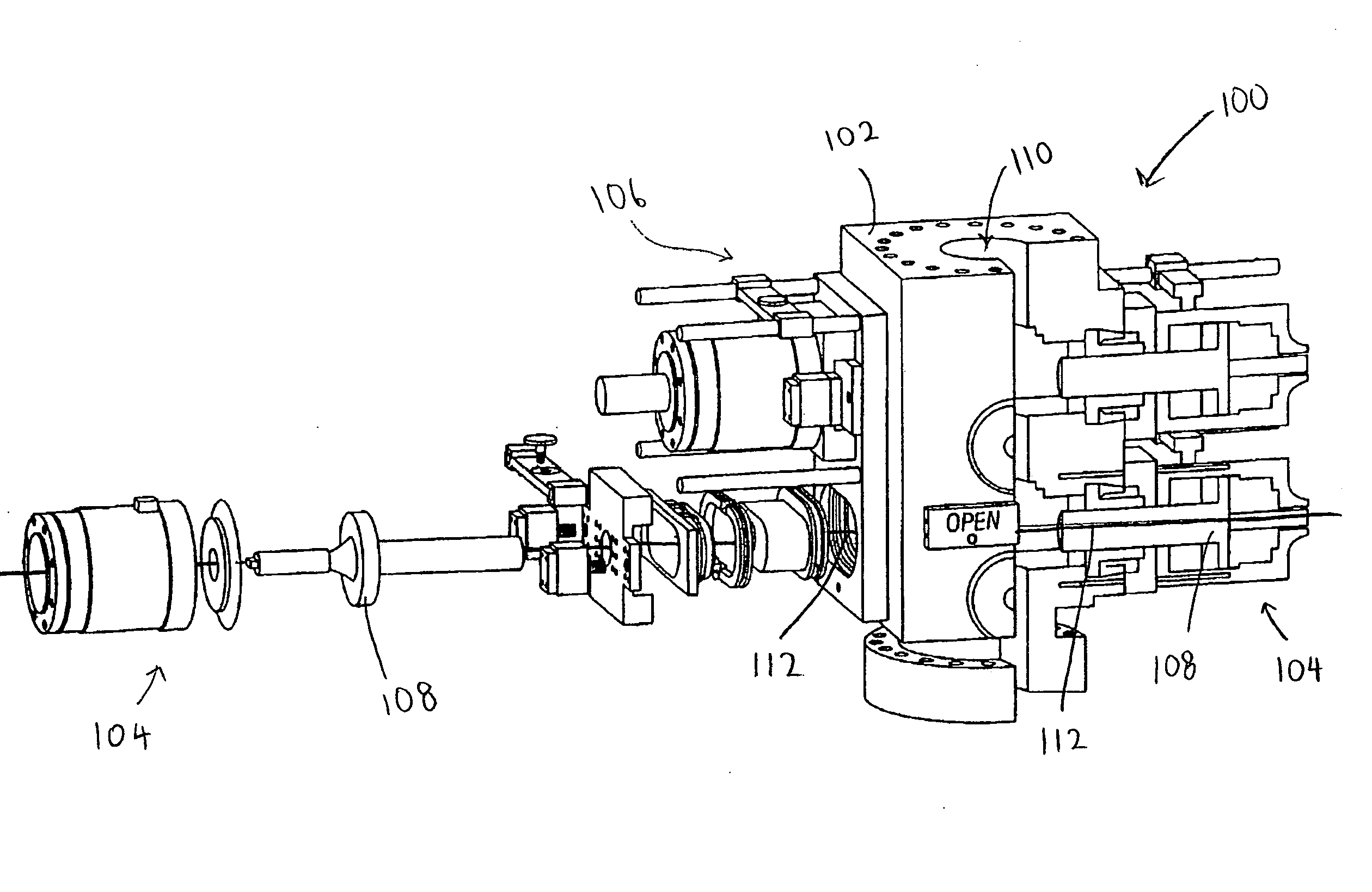
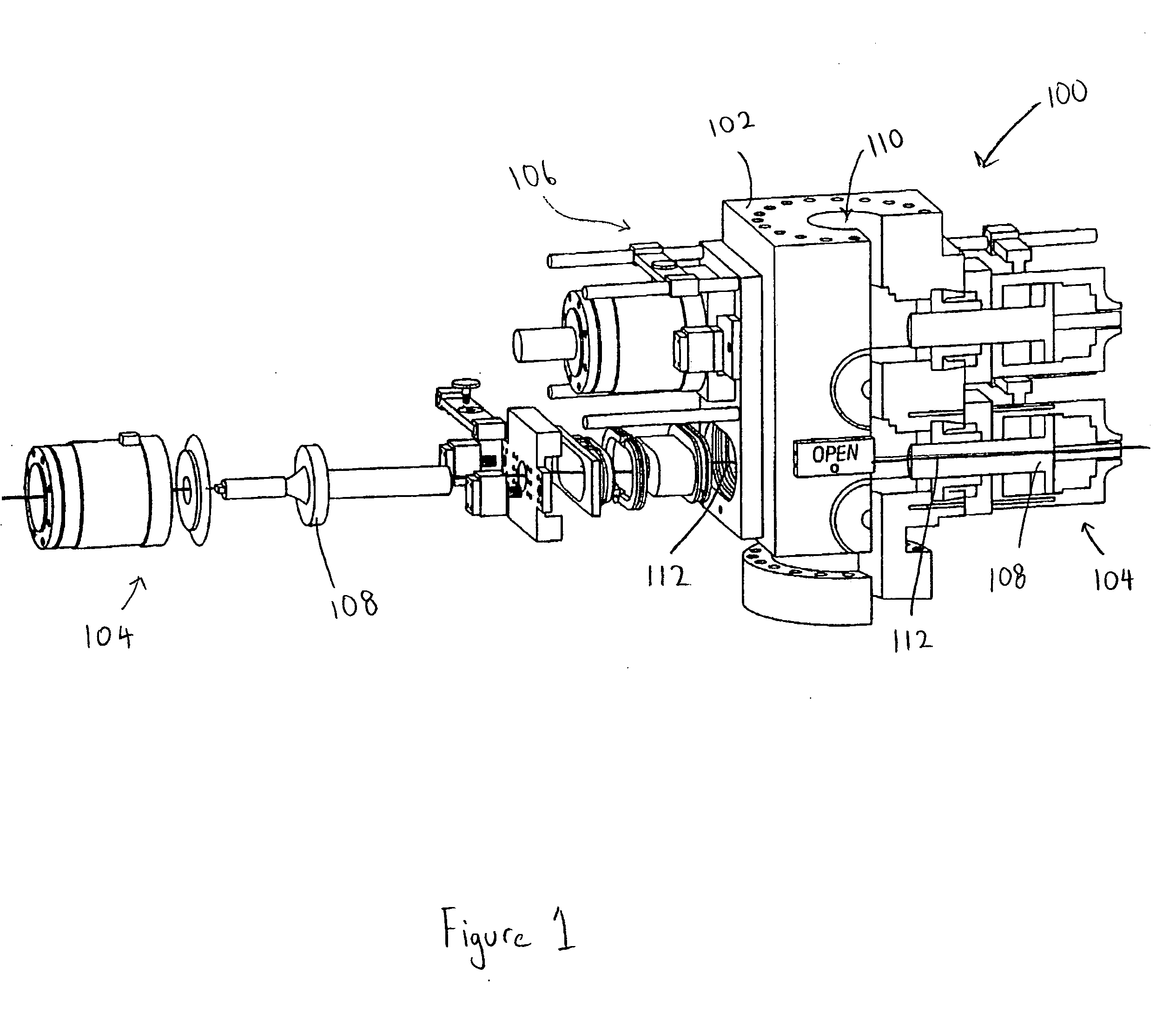
[0035]In one aspect, embodiments disclosed herein provide for an apparatus to seal between high-pressure and low-pressure zones. In another aspect, embodiments disclosed herein provide for an apparatus to seal between a bonnet and a bore of a ram-type blowout preventer. Further, in another aspect, embodiments disclosed herein provide a sealing apparatus to seal between a bonnet and a bore of a ram-type blowout preventer under both high pressure and low pressure.

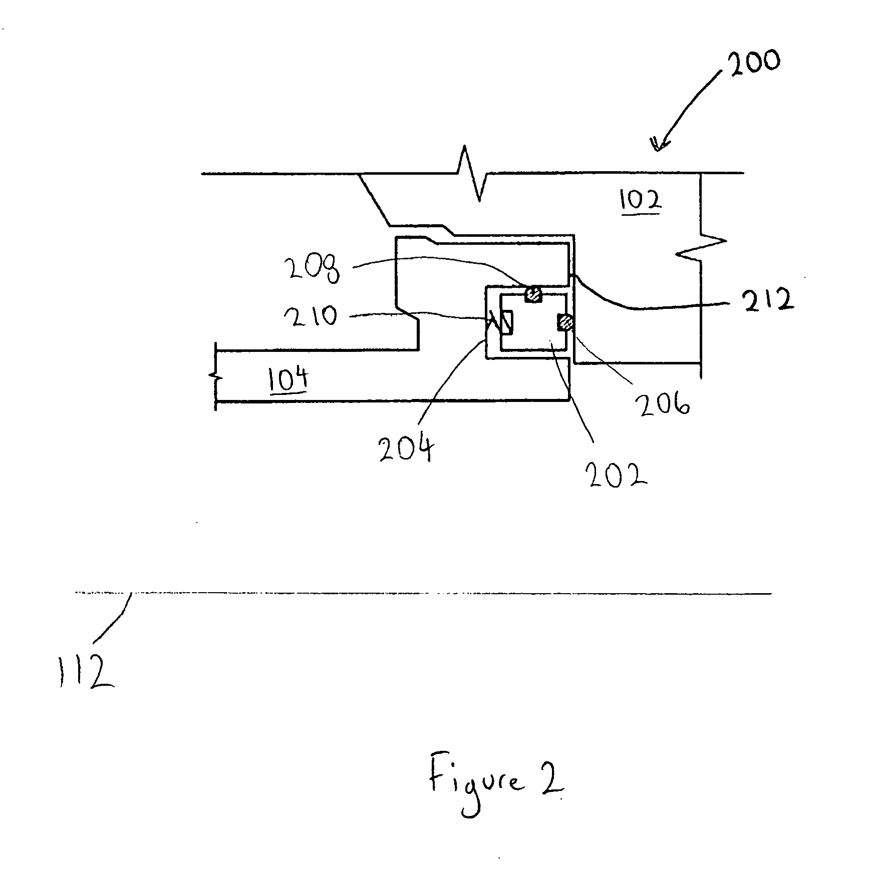
[0036]Referring now to FIGS. 5A and 5B, a seal assembly 500 in accordance with an embodiment of the present disclosure is shown. FIG. 5A shows a cross section of the entire seal assembly 500 shown in FIG. 5B. In FIG. 5B, seal assembly is depicted as having an oval shape, as may be used about a bonnet of a ram-type blowout preventer, but those having ordinary skill in the art will appreciate that the present invention is not limited to any particular shape. For example, in another embodiment, the seal assembly may be of a circ...


PUM


Abstract

A seal assembly disposed within a radial seal groove to sealingly engage a bonnet within a bore. The seal assembly includes a radial seal surface, an axial seal surface, a vent surface, and an axial preload surface. The seal assembly is thrust towards a longitudinal wall and away from a radial wall of the radial seal groove when pressure in a high-pressure zone increases.

Description

BACKGROUND OF INVENTION[0001]1. Field of the Invention[0002]Embodiments disclosed herein generally relate to blowout preventers used in the oil and gas industry. Specifically, embodiments selected relate to blowout preventers with a novel seal assembly to seal between high-pressure and low-pressure zones.[0003]2. Background Art[0004]Well control is an important aspect of oil and gas exploration. When drilling a well, for example, safety devices must be put in place to prevent injury to personnel and damage to equipment resulting from unexpected events associated with the drilling activities.[0005]Drilling wells involves penetrating a variety of subsurface geologic structures, or “layers.” Occasionally, a wellbore will penetrate a layer having a formation pressure substantially higher than the pressure maintained in the wellbore. When this occurs, the well is said to have “taken a kick.” The pressure increase associated with a kick is generally produced by an influx of formation flui...

Claims


Application Information

Patent Timeline
IPC IPC(8): E21B33/06
CPCE21B33/061F16J15/164F16J15/166
Inventor BERCKENHOFF, MICHAEL WAYNE
Owner HYDRIL USA DISTRIBUTION LLC
Why Eureka
Eureka Blog
Learn More