Wheel Allignment Angle Measuring Apparatus and Wheel Alignment Angle Measuring Method

a technology of allignment angle and measuring apparatus, which is applied in the direction of mechanical measuring arrangement, instruments, and using mechanical means, etc., can solve the problem that the temporal change of the lateral force generated in the front wheel cannot be sufficiently approximated to the temporal chang

Inactive Publication Date: 2008-01-31
BRIDGESTONE CORP
View PDF6 Cites 4 Cited by
  • Summary
  • Abstract
  • Description
  • Claims
  • Application Information

AI Technical Summary

Benefits of technology

[0012] For this reason, the non-reference wheel setting alignment angle can be specified easily and reliably. This is because it is not necessary to execute complicated processing of approximating temporal changes of the lateral force Fy generated in the non-reference wheel to temporal changes of the lateral force Fy generated in the reference wheel, while the complicated processing is required in the above described conventional alignment angle (toe angle) adjusting method.
[0025] In essence, according to the characteristics of the present invention, it is possible to provide a wheel alignment angle measuring apparatus and a wheel alignment angle measuring method, which are capable of determining a value of an alignment angle allowing characteristics of lateral forces generated respectively in a front wheel and in a rear wheel to be approximated to each other in the case of adjusting an alignment angle of a wheel based on a characteristic of the lateral forces generated in the wheels.

Problems solved by technology

However, the above described method of adjusting an alignment angle (a toe angle) has had a problem that should be solved for improvement.
That is, there has been a problem that, depending on a kind or the like of a vehicle, a pneumatic tire or a tire wheel, there is a case where temporal changes of the lateral force Fy generated in the front wheel cannot be sufficiently approximated to the temporal changes of the lateral force Fy generated in the rear wheel.

Method used


Image

  • Wheel Allignment Angle Measuring Apparatus and Wheel Alignment Angle Measuring Method
  • Wheel Allignment Angle Measuring Apparatus and Wheel Alignment Angle Measuring Method
  • Wheel Allignment Angle Measuring Apparatus and Wheel Alignment Angle Measuring Method

Examples


Embodiment Construction

Configuration of wheel alignment angle measuring system including wheel alignment angle measuring apparatus)

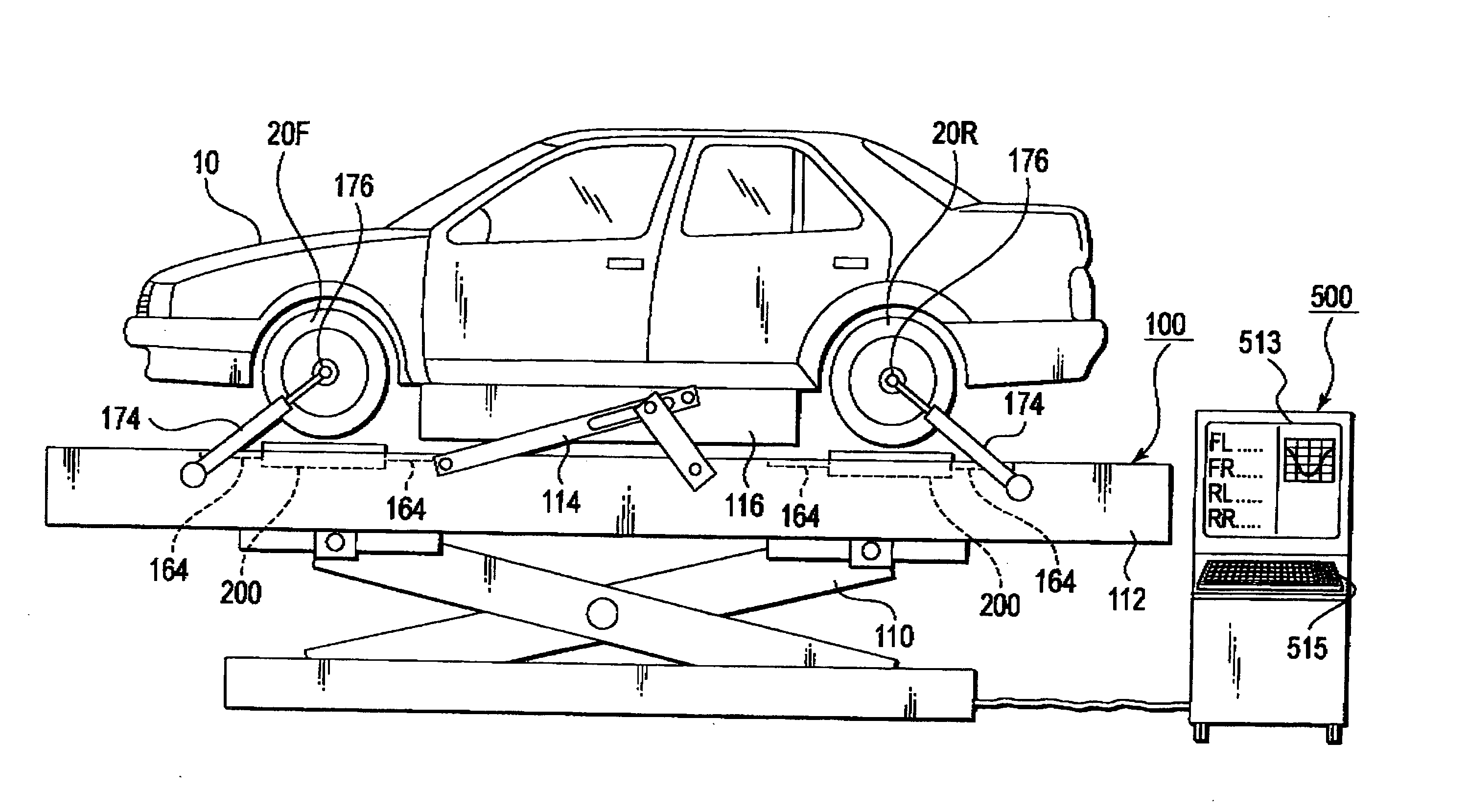
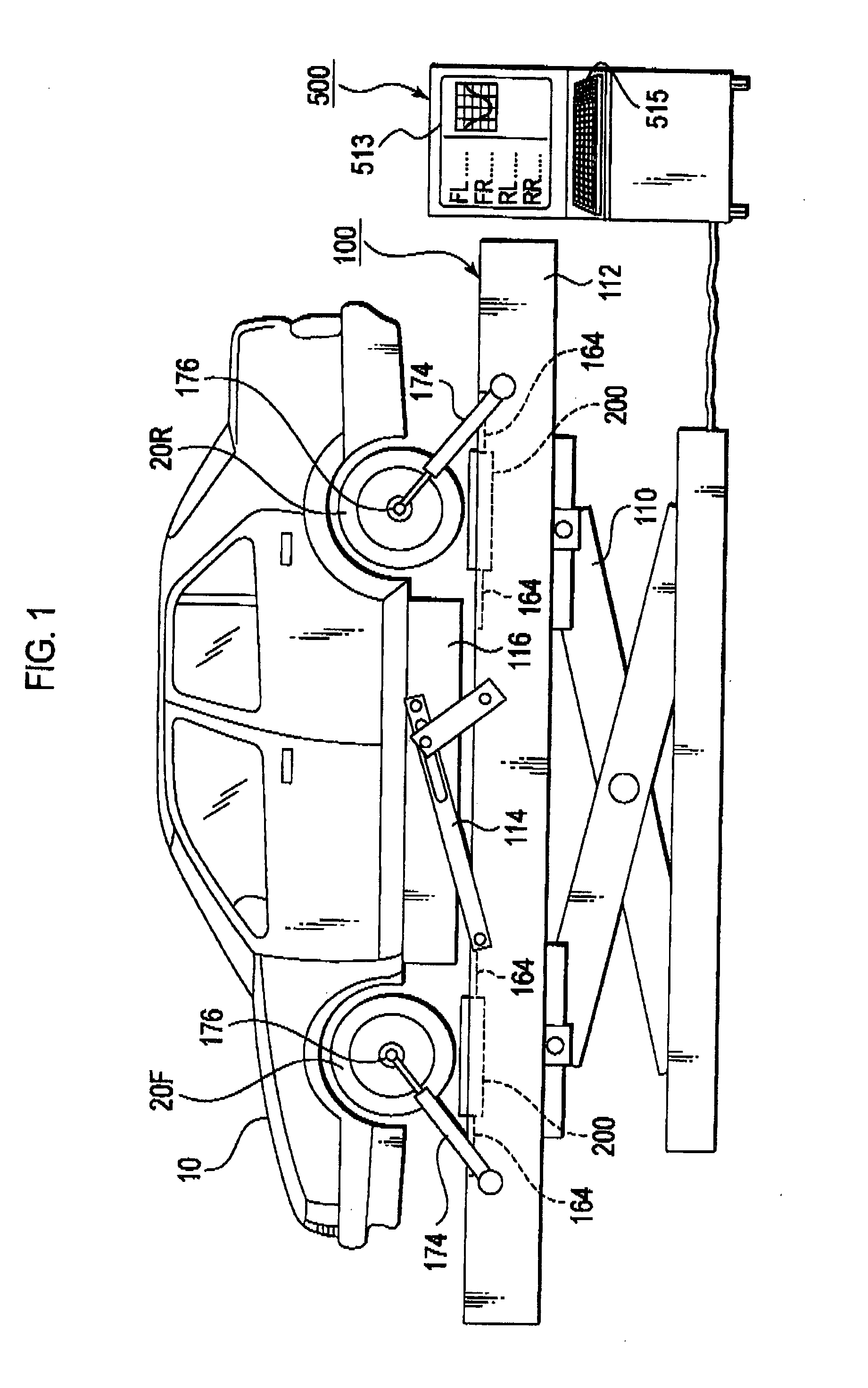
[0039] Next, with reference to the drawings, description will be given of a configuration of a wheel alignment angle measuring system including a wheel alignment angle measuring apparatus according to an embodiment of the present invention. Note that, in the following description on the drawings, the corresponding or like reference numerals are attached to corresponding or like elements. However, it should be noted that the drawings are schematic, and that ratios of some measurements to others, and the like, are not to scale. Therefore, specific measurements should be judged in consideration of the following description, Additionally, it goes without saying that the respective drawings include parts whose relation and ratio vary also between any ones of the drawings.

(1) Entire Schematic Configuration

[0040] First of all, an entire configuration of the wheel alignment angle...


PUM


Abstract

A wheel alignment angle measuring apparatus according to the present invention computes variation energy sums EA″ and EB″ and a reference wheel referencing alignment angle (a toe angle TBR) based on an anteroposterior force variation rate dFx and a lateral force variation rate dFy generated in a reference wheel (RL). Furthermore, the alignment angle measuring apparatus computes a non-reference wheel referencing alignment angle (a toe angle TNBR) of a non-reference wheel (FL), and then computes a toe angle TNBA to be specified for the non-reference wheel, based on the toe angle TNBR and a difference between a toe angle TBR and the toe angle TI. According to the thus configured wheel alignment angle measuring apparatus, it is possible to determine a value of an alignment angle that allows characteristics of lateral forces generated in front and rear wheels to be approximated to each other, when the alignment angles of wheels are adjusted based on the characteristics of the lateral forces generated in the wheels.

Description

TECHNICAL FIELD [0001] The present invention relates to a wheel alignment angle measuring apparatus and a wheel alignment angle measuring method, which are used for measuring alignment angles of wheels mounted on a vehicle. BACKGROUND ART [0002] For a wheel of a four-wheeled motor vehicle (hereinafter, as appropriate, referred to as a vehicle in short) such as a passenger automobile, certain “alignment angles” including a camber angle (an angle formed by a longitudinal center line of the wheel and a plumb line when the wheel mounted on the vehicle is viewed from a front face of the vehicle), a toe angle (an angle formed by a horizontal diameter line (a equatorial line) of the wheel, and a straight line passing the anteroposterior center of the vehicle when the vehicle travels straight forward), and a caster angle (an angle formed by a king pin shaft and a plumb line when the wheel is viewed from a side face of the vehicle) are generally determined in consideration of: obtainment of ...

Claims


Application Information

Patent Timeline
Patent Type & Authority Applications(United States)
IPC IPC(8): G01B5/255
CPCG01B21/26G01M17/007G01B2210/22
Inventor NARUSE, YUTAKA
Owner BRIDGESTONE CORP
Why Eureka
Try Eureka