
Input interface including push-sensitive mechanical switch in combination with capacitive touch sensor

Inactive Publication Date: 2008-01-31
SLACKER
View PDF25 Cites 30 Cited by
  • Summary
  • Abstract
  • Description
  • Claims
  • Application Information

AI Technical Summary

Benefits of technology

[0007] The present invention also relates to a method of controlling a display interface of an electronic device using an input interface of the device. The method includes generating, upon touching by a user of a surface of the input interface, a first input signal. The method further includes generating, upon application by the user of a pushing force to the s

Problems solved by technology

However, one consequence of this ease of portability tends to be false or spurious actuation of the input interface of the portable unit.
Such spurious actuation may arise when attempting to retrieve other objects from a pocket or purse containing the portable device, or when the unit is bumped or otherwise impacted while so contained.
Spurious activation may also occur when a user is attempting to actuate a particular input element (e.g., a button or key) while the portable device is out of view and inadvertently engages a different input element.
Since portable electronic devices may be used in a variety of environments, including dark areas or areas with insufficient ambient light for viewing of its input elements, it is often difficult to control the device without moving to an area with adequate lighting.
Although some devices are configured to activate a display backlight or other lighting element upon depression of a key or button, such illumination of the display can consume substantial power and the triggering key press may result in the unintended input of information or commands into the device.
However, the requirement that a predefined period of time expire prior to entry into hibernate mode means that existing devices tend to stay illuminated or “backlit” too long after being put away in a pocket or purse, resulting in a waste of precious power.
Unfortunately, both of these circumstances tend to result in user dissatisfaction and even irritation.

Method used


Image

  • Input interface including push-sensitive mechanical switch in combination with capacitive touch sensor
  • Input interface including push-sensitive mechanical switch in combination with capacitive touch sensor
  • Input interface including push-sensitive mechanical switch in combination with capacitive touch sensor

Examples


Embodiment Construction

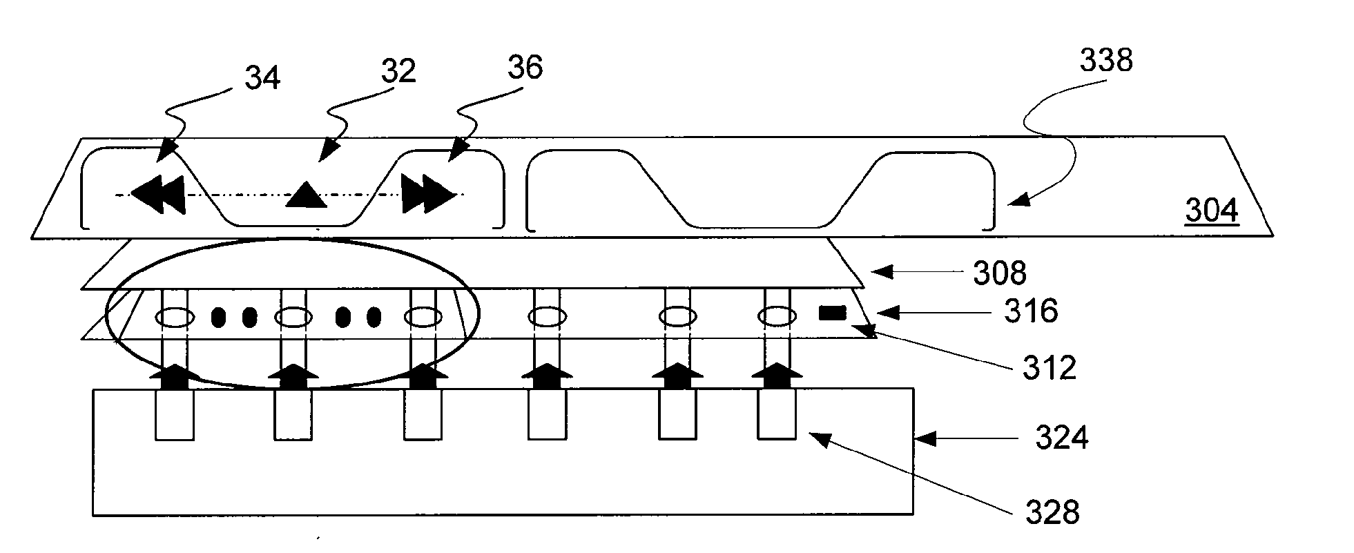
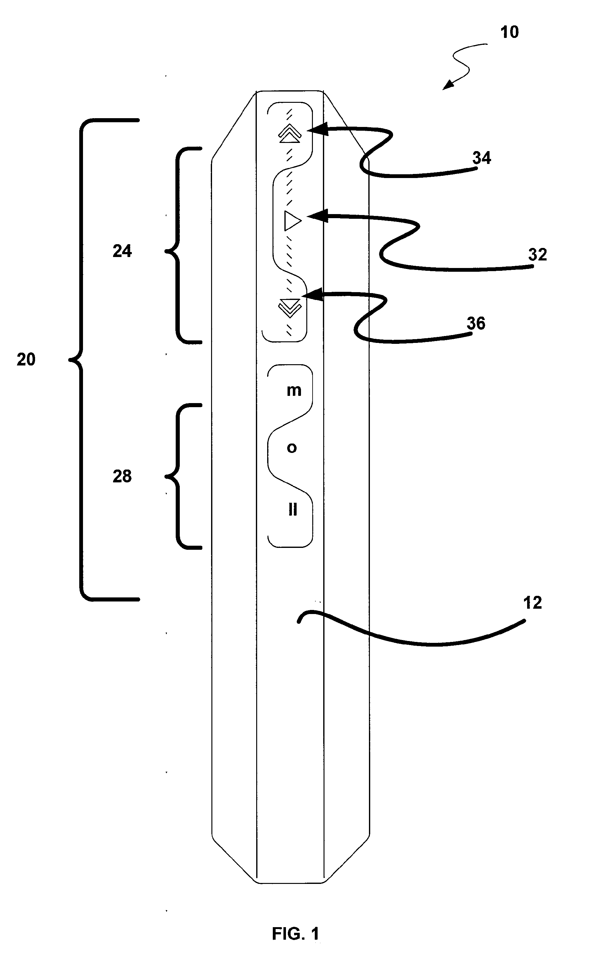
[0016] Embodiments of the invention generally relate to an input interface for a portable or other electronic unit comprised of a push-sensitive element in combination with a touch-sensitive element. In an exemplary embodiment the push-sensitive element is comprised of a mechanical switch and the touch-sensitive element comprises a capacitive-resistant control responsive to skin contact. The inventive input interface advantageously limits accidental and other spurious actuation of the input interface and the required range of finger motion.

[0017] A method of providing user input to a portable electronic unit in accordance with one embodiment of the invention comprises detecting that skin contact has been made with at least one control portion of the input interface. Such detection does not result in actuation of the control portion of the input interface, but may cause illumination of such portion for the benefit of the user. Once such detection of skin contact has occurred, actuat...


PUM


Abstract

An input interface for an electronic device is disclosed. The input interface includes a touch-sensitive switch supported by a board member. The input interface further includes a push-sensitive switch supported by a circuit board. The board member and circuit board will typically be generally planar and included within substantially parallel layers of the input interface. The touch-sensitive switch and push-sensitive switch form a switch pair that may be associated with a display control function invoked upon actuation of both of the switches.

Description

CROSS-REFERENCE TO RELATED APPLICATIONS [0001] This application claims priority under 35 U.S.C. §119(e) to co-pending U.S. Provisional Application Ser. No. 60 / 806,716, entitled INPUT INTERFACE INCLUDING PUSH-SENSITIVE MECHANICAL SWITCH IN COMBINATION WITH CAPACITIVE TOUCH SENSOR, and to co-pending U.S. Provisional Application Ser. No. 60 / 886,283, entitled DEVICES AND METHODS FOR DISTRIBUTING DIGITAL CONTENT, both of which are incorporated by reference herein for all purposes.BACKGROUND OF THE INVENTION [0002] Portable electronic devices have become increasingly popular in recent years, since such devices may be easily carried in, for example, a pocket, handbag, or purse. However, one consequence of this ease of portability tends to be false or spurious actuation of the input interface of the portable unit. Such spurious actuation may arise when attempting to retrieve other objects from a pocket or purse containing the portable device, or when the unit is bumped or otherwise impacted...

Claims


Application Information

Patent Timeline
IPC IPC(8): H02B13/00G05B1/01
CPCG06F3/03547G06F2203/0339G06F3/038
Inventor MUDD, DENNIS M.CSICSATKA, TIBORPARISE, DAVIDBENAVIDEZ, DAVIDMEHIN, AFSHINHARDEN, DAN
Owner SLACKER
Learn More