
USB port locking and blocking device

a technology for usb ports and locking devices, applied in the direction of locking applications, coupling devices, portable object locks, etc., can solve the problems of reducing affecting the service life of the device, and bending out of shape with repeated use, so as to reduce the rearward movement

Active Publication Date: 2008-02-21
ACCO BRANDS USA LLC
View PDF12 Cites 36 Cited by
  • Summary
  • Abstract
  • Description
  • Claims
  • Application Information

AI Technical Summary

Benefits of technology

[0011]In a first exemplary embodiment, a locking mechanism includes a front spring-loaded set of pins, which is biased backwards, cooperating with a rear set of pins. A locking latch cooperates with a notch in the lock housing to restrict rearward movement of the locking mechanism and linear cam. A linear cam return spring biases the locking mechanism and linear cam rearward, and a locking latch return spring biases the rear portion of the locking mechanism sideways, at which position the locking latch prevents rearward movement of the linear cam, retaining the lock in its locked position.

Problems solved by technology

This can be a security problem.
While others have attempted to solve this problem with locks including a control shaft which, when slid forward (i.e. toward the USB port), forces a claw on the back end of a resilient tab outward into a slot in the USB port, such a claw may become jammed inward with too much force or bent out of shape with repeated use.
In addition, such a lock is capable of blocking use of only a single USB port, and does not address the issue of necessary external devices such as keyboards and mice.

Method used


Image

  • USB port locking and blocking device
  • USB port locking and blocking device
  • USB port locking and blocking device

Examples


Embodiment Construction

[0030]Exemplary embodiments of the present invention will hereinafter be described in detail with reference to the accompanying drawings.

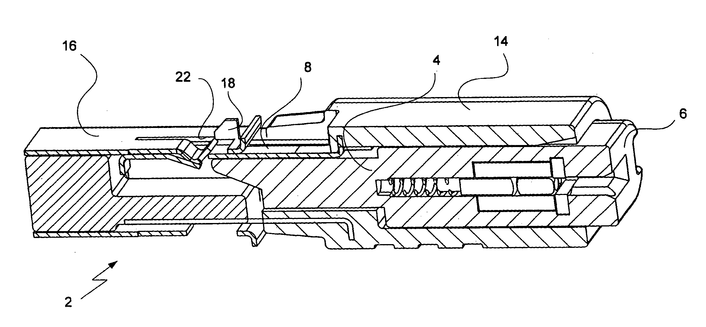
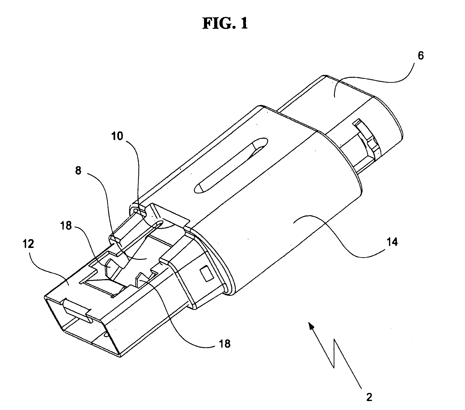
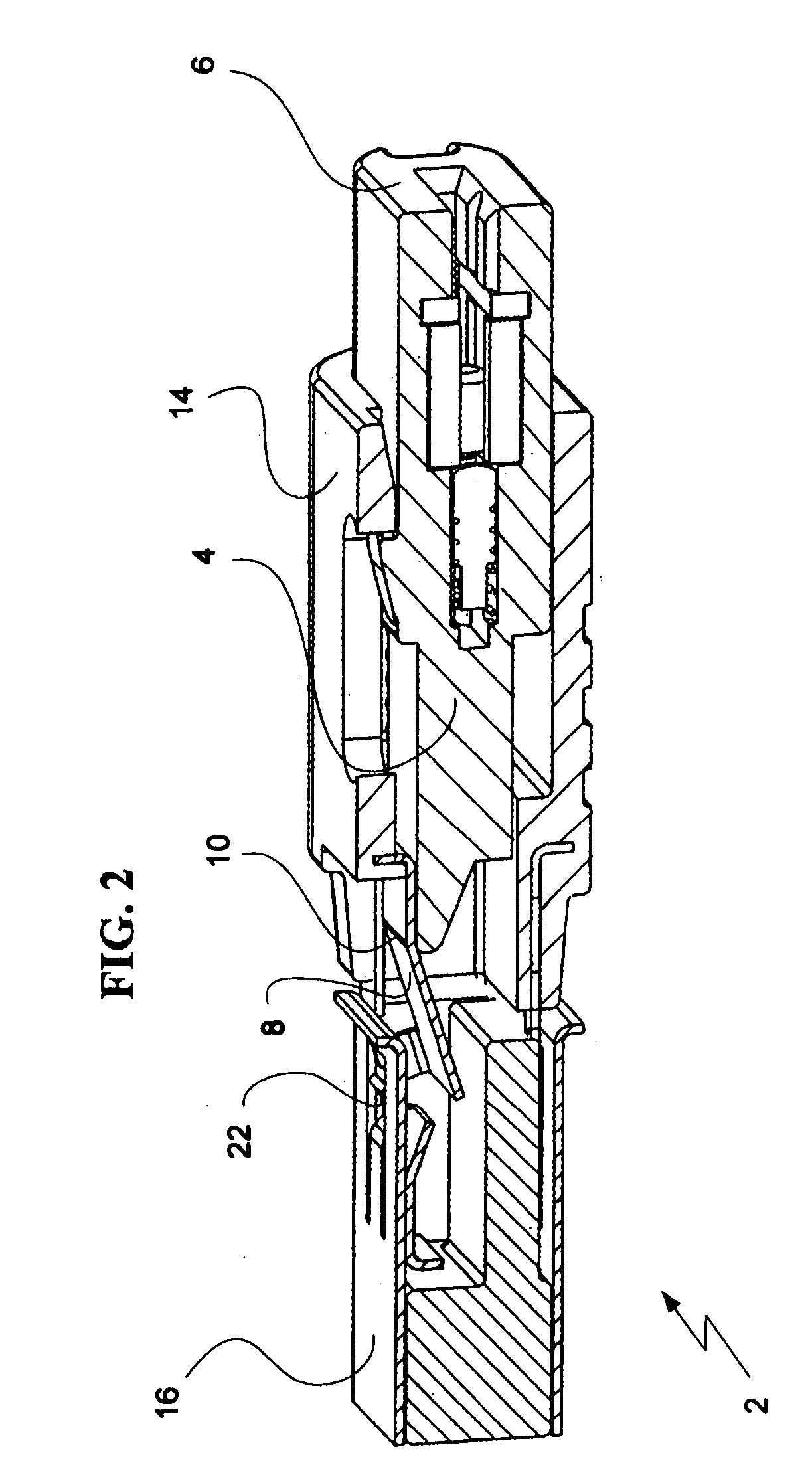
[0031]Referring to FIG. 1, an exemplary embodiment of the present invention provides a lock 2 with a housing 14 mounted onto a retaining sheath 12, which is insertable to a USB port. Locking member 8 is pivotally connected to the rear end of retaining sheath 12. Locking member 8 is provided with two protrusions 18, which correspond to standard openings in a USB port. Locking member 8 has a bent, preformed shape, such that in the absence of external forces it runs diagonally; its front end is farther inward than its back end 10. Lock 2 further includes lock button 6 which protrudes from the rear end of housing 14. Lock button 6 is depressible by a user to lock the lock 2. Referring also to FIGS. 2 and 3, lock button 6 is connected to linear cam 4, which pivots locking member 8 by cooperating with the ramped camming surface of locking member 8.

[0032]...


PUM


Abstract

Locking and blocking devices for USB ports include a lock having a linear cam with a lock button at its back end, and a locking member pivotally connected at its back end to a retaining sheath such that forward sliding of the linear cam pivots the locking member outwards. The front end of the locking member is biased toward the interior of the lock. The locking member has protrusions at its front end configured for insertion into holes of a USB port. A blocking plate includes at least one opening configured for insertion of the retaining sheath. A retaining bracket has a back face that defines a first opening, wider than the cable that connects a plug to an external device. The front face of the bracket defines a second opening configured for insertion of the retaining sheath, and a third opening configured for insertion of the plug.

Description

CROSS-REFERENCE TO RELATED APPLICATION[0001]This application claims priority to, and the benefit of, U.S. Provisional Application No. 60 / 838,591, filed on Aug. 17, 2006, the entire contents of which are incorporated herein by reference.BACKGROUND OF THE INVENTION[0002](a) Field of the Invention[0003]The present invention relates to a lock for USB ports on personal computers and other electronic devices. More particularly, the present invention relates to a locking device for locking and / or blocking a USB port and adjacent ports to prevent use of or removal of a cable from one or more ports.[0004](b) Description of the Related Art[0005]Generally, universal serial bus (USB) ports provide a serial bus standard for connecting devices to computers. Most modern computers include at least one USB port. USB ports can also be used on video game consoles and personal digital assistants (PDAs), and even devices like televisions and home stereo equipment. They are used to connect peripherals su...

Claims


Application Information

Patent Timeline
Patent Type & Authority Applications(United States)
IPC IPC(8): E05B65/00
CPCH01R2201/06H01R13/6397Y10T70/5009Y10T70/40Y10T70/50
Inventor POPPE, CARL H.
Owner ACCO BRANDS USA LLC
Learn More