Tip Turbine Engine Comprising A Nonrotable Compartment

Inactive Publication Date: 2008-02-21
UNITED TECH CORP
View PDF86 Cites 4 Cited by
  • Summary
  • Abstract
  • Description
  • Claims
  • Application Information

AI Technical Summary

Benefits of technology

[0010] The present invention therefore provides a lightweight lubricating fluid system for a tip turbine engine which is compac

Problems solved by technology

The axial flow relationship results in a relatively complicated elongated engine structure of considerable longitudinal length re

Method used


Image

  • Tip Turbine Engine Comprising A Nonrotable Compartment
  • Tip Turbine Engine Comprising A Nonrotable Compartment
  • Tip Turbine Engine Comprising A Nonrotable Compartment

Examples


Example

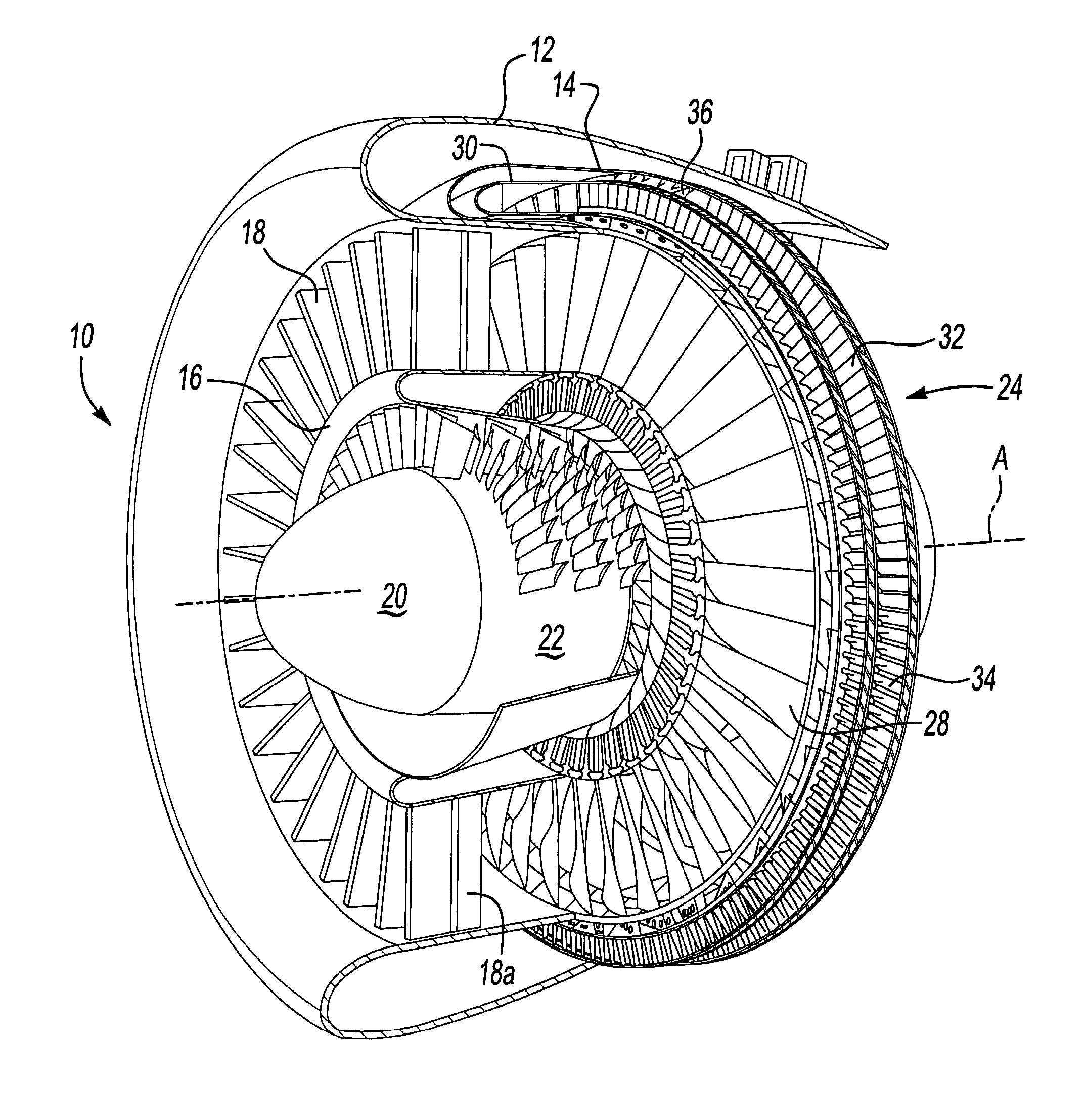
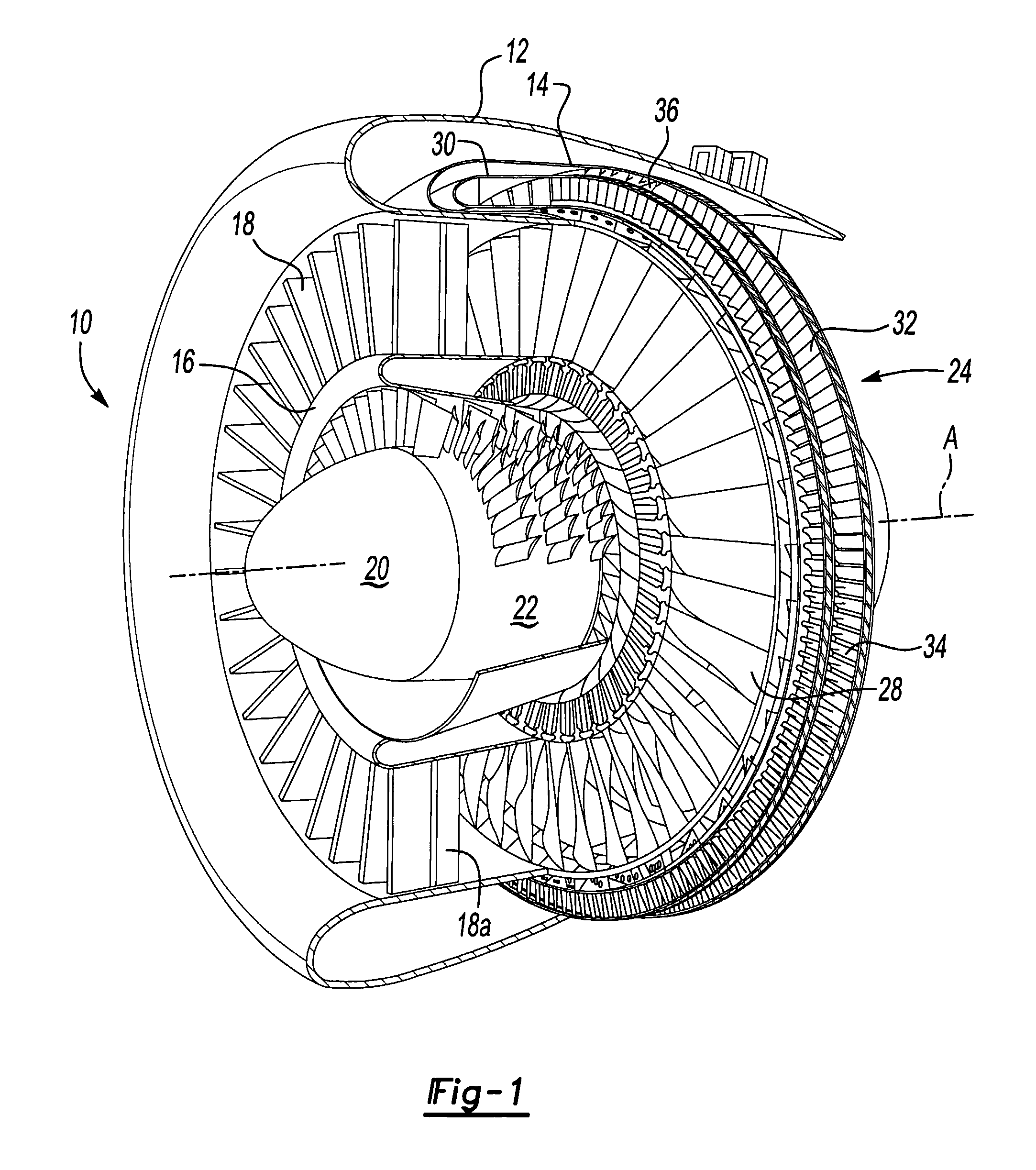
[0017]FIG. 1 illustrates a general perspective partial sectional view of a tip turbine engine type gas turbine engine 10. The engine 10 includes an outer nacelle 12, a nonrotatable static outer support structure 14 and a nonrotatable static inner support structure 16. A multitude of fan inlet guide vanes 18 are mounted between the static outer support structure 14 and the static inner support structure 16. Each inlet guide vane preferably includes a variable trailing edge 18A.

[0018] A nose cone 20 is preferably located along the engine centerline A to smoothly direct airflow into an axial compressor 22 adjacent thereto. The axial compressor 22 is mounted about the engine centerline A behind the nose cone 20.

[0019] A fan-turbine rotor assembly 24 is mounted for rotation about the engine centerline A aft of the axial compressor 22. The fan-turbine rotor assembly 24 includes a multitude of hollow fan blades 28 to provide internal, centrifugal compression of the compressed airflow fro...


PUM


Abstract

A non-rotating compartment along an engine centerline of a tip turbine engine is defined between an inner support housing, an outer support housing and an aft housing. The non-rotating compartment provides a space that may be utilized for a multitude of engine accessories and components including an engine lubricating fluid system.

Description

[0001] This invention was made with government support under Contract No.: F33657-03-C-2044. The government therefore has certain rights in this invention.BACKGROUND OF THE INVENTION [0002] The present invention relates to a tip turbine engine, and more particularly to a non-rotating compartment located along an engine centerline. [0003] An aircraft gas turbine engine of the conventional turbofan type generally includes a forward bypass fan, a compressor, a combustor, and an aft turbine all located along a common longitudinal axis. A compressor and a turbine of the engine are interconnected by a shaft. The compressor is rotatably driven to compress air entering the combustor to a relatively high pressure. This pressurized air is then mixed with fuel in a combustor and ignited to form a high energy gas stream. The gas stream flows axially aft to rotatably drive the turbine which rotatably drives the compressor through the shaft. The gas stream is also responsible for rotating the byp...

Claims


Application Information

Patent Timeline
IPC IPC(8): F01D25/24
CPCF02C3/073F02C3/08F02C7/32F05D2260/40311F02K3/02F02K3/068F02C7/36
Inventor SUCIU, GABRIEL L.MERRY, BRIANPORTLOCK, LAWRENCE
Owner UNITED TECH CORP
Why Eureka
Try Eureka