Coupling with Latch Mechanism

a technology of latch mechanism and latch plate, which is applied in the direction of couplings, hose connections, engine seals, etc., can solve the problems of male inserts that may not be compatible with the latch plate above, may not be compatible with the latch plate, and may not be reliable and reliabl

Active Publication Date: 2008-03-13
COLDER PRODS
View PDF12 Cites 25 Cited by
  • Summary
  • Abstract
  • Description
  • Claims
  • Application Information

AI Technical Summary

Benefits of technology

[0013] In one preferred embodiment, the latch plate is slidably mounted within a groove formed through the body, where the groove extends transversely of the first bore. The latch plate defines a main portion having a top end and a bottom end. The latch plate includes an annular aperture disposed between the top and bottom ends and being in fluid communication with the first bore. A lever portion is disposed proximate the top end of the main portion. The lever portion enables the latch plate to reciprocate within the groove in a released position and a latched position. A raised edge is circumferentially disposed about a portion of the annular aperture. The raised edge is disposed proximate the bottom end and extending radially inward of the annular aperture.

Problems solved by technology

The latch plate of the latch mechanism above, however, may still experience problems in reliability and performance.
In this configuration of an inner edge, the male insert may unfavorably cam out and become separated from the female coupling assembly during use.

Method used


Image

  • Coupling with Latch Mechanism
  • Coupling with Latch Mechanism
  • Coupling with Latch Mechanism

Examples


Embodiment Construction

[0044] In the following description of the illustrated embodiments, reference is made to the accompanying drawings that form a part hereof, and in which is shown by way of illustration of the embodiments in which the invention may be practiced. It is to be understood that other embodiments may be utilized as structural changes may be made without departing from the spirit and scope of the present invention.

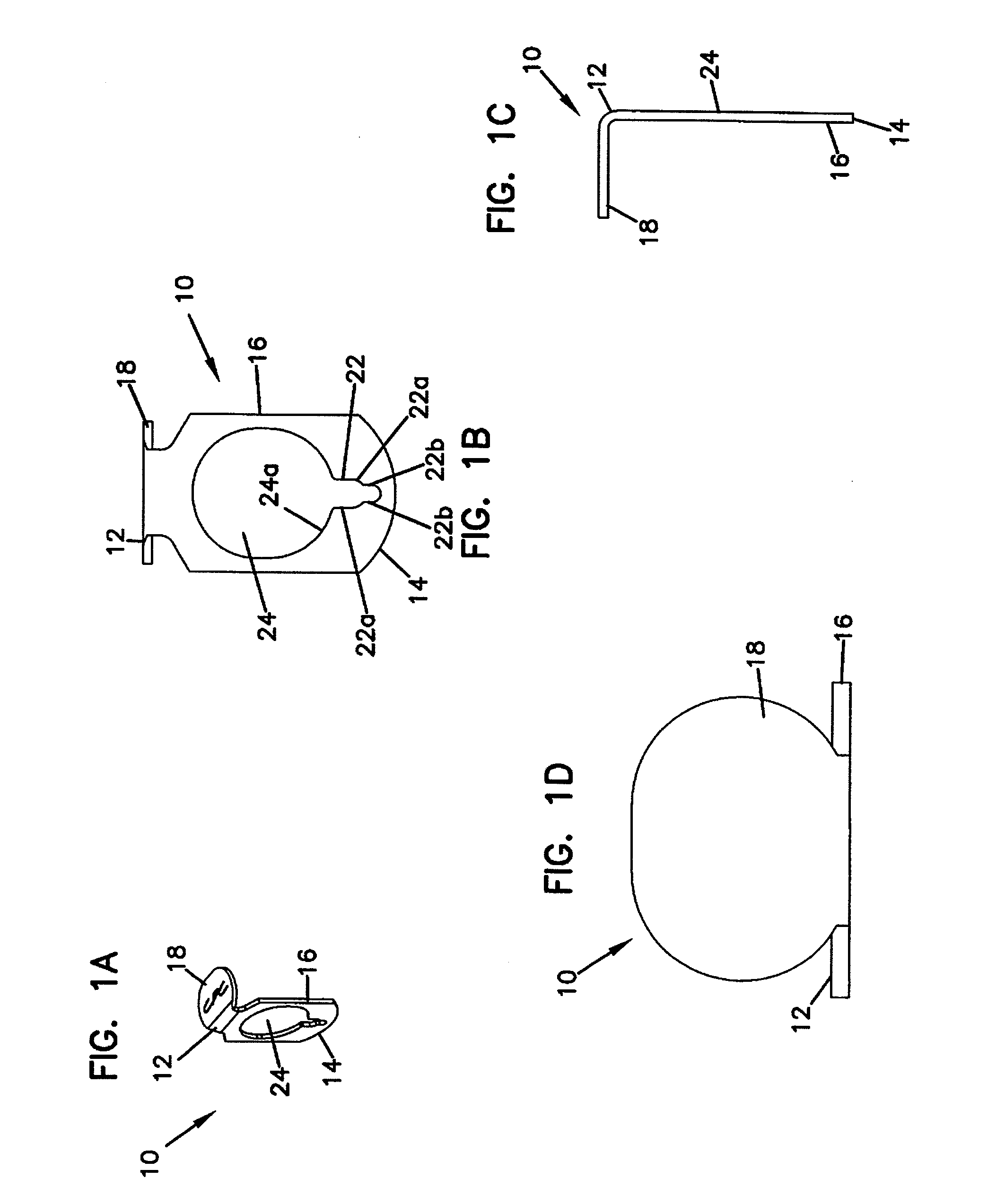
[0045]FIGS. 1A through 1D illustrate a known latch plate 10 for a latch mechanism typically used in quick connect / disconnect couplings. The latch plate 10 is structured and configured similarly as the latch plate 80 of U.S. Pat. No. 5,033,777 (hereinafter Patent '777). The latch plate 10 can be mounted on the female coupling assembly 14 of Patent '777 in the same manner. The latch plate 10 is used to latch and release a mating insert, such as the male insert 12 of Patent '777. The latch plate 10 includes a top end 12 and a bottom end 14, and defines a main portion 16 and a lever ...


PUM


Abstract

A coupling apparatus having coupling body with a mechanical latch assembly. The mechanical latch assembly includes a modified latch plate. The latch plate defines a main portion having a top end and a bottom end and includes an annular aperture disposed between the top and bottom ends. A lever portion is disposed proximate the top end. The lever portion enables the latch plate to move within a coupling body, so as to operate the mechanical latch assembly in a released position and a latched position. A raised edge is disposed about a portion of the annular aperture. The raised edge is disposed proximate the bottom end and extends radially inward of the inner edge defined by the annular aperture. A pin opening is disposed proximate the bottom end opposite of the lever portion. The pin opening is positioned radially outward from the annular aperture, and defines a separate enclosed edge.

Description

FIELD OF INVENTION [0001] The invention is related to a fluid connector with a latch mechanism. More particularly, the present invention is related to a fluid coupling having a latch mechanism with an improved latch plate structure. The latch mechanism is used in fluid couplings for quick connection / disconnection of tubings in pressured fluid conveyance conditions. BACKGROUND OF THE INVENTION [0002] Connectors for fluid transport are common and widely used. Typically, such connectors often employ a female coupling that connects with a male insert member. These couplings provide a structure that can be readily coupled and uncoupled from a male insert member using a quick connect / disconnect configuration. To achieve this quick connect / disconnect configuration, a latch mechanism usually is incorporated with the coupling. Such mechanical latches provide a releasable lock mechanism for connecting and retaining a male insert member to the coupling, so that sealing surfaces of a coupling a...

Claims


Application Information

Patent Timeline
Patent Type & Authority Applications(United States)
IPC IPC(8): F16L39/00F16L37/084
CPCF16L37/42F16L37/0841
Inventor SCHMIDT, MARK F.
Owner COLDER PRODS
Why Eureka
Try Eureka