
Backlight module and flat panel display

a technology of backlight module and flat panel display, which is applied in the direction of lighting and heating apparatus, planar/plate-like light guides, instruments, etc., can solve the problems of glass breaking in liquid crystal panel modules, and achieve the effect of reducing poor displaying phenomenon and intensive stress for

Inactive Publication Date: 2008-03-13
CHUNGHWA PICTURE TUBES LTD
View PDF3 Cites 10 Cited by
  • Summary
  • Abstract
  • Description
  • Claims
  • Application Information

AI Technical Summary

Benefits of technology

[0006]In order to solve the problems mentioned above, the present invention provides a backlight module with a frame. The frame has the structure of a supporting rack, which has an angle between the optical film, to support the stress force from the cover. The supporting rack causes the broader touching area to bear the intensive stress force and reduce poor displaying phenomenon.

Problems solved by technology

Sometimes, it may seriously cause glasses break in liquid crystal panel module.

Method used


Image

  • Backlight module and flat panel display
  • Backlight module and flat panel display
  • Backlight module and flat panel display

Examples


Embodiment Construction

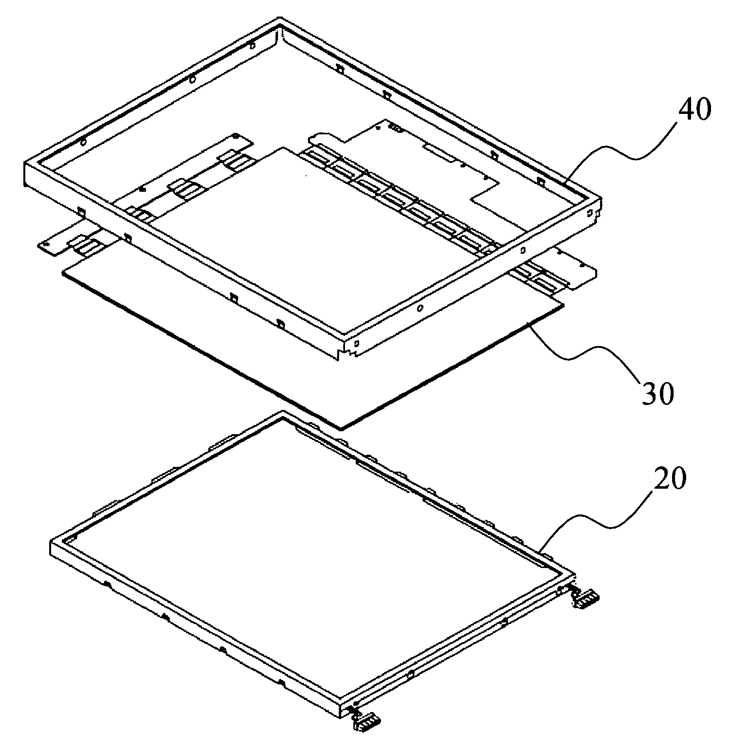
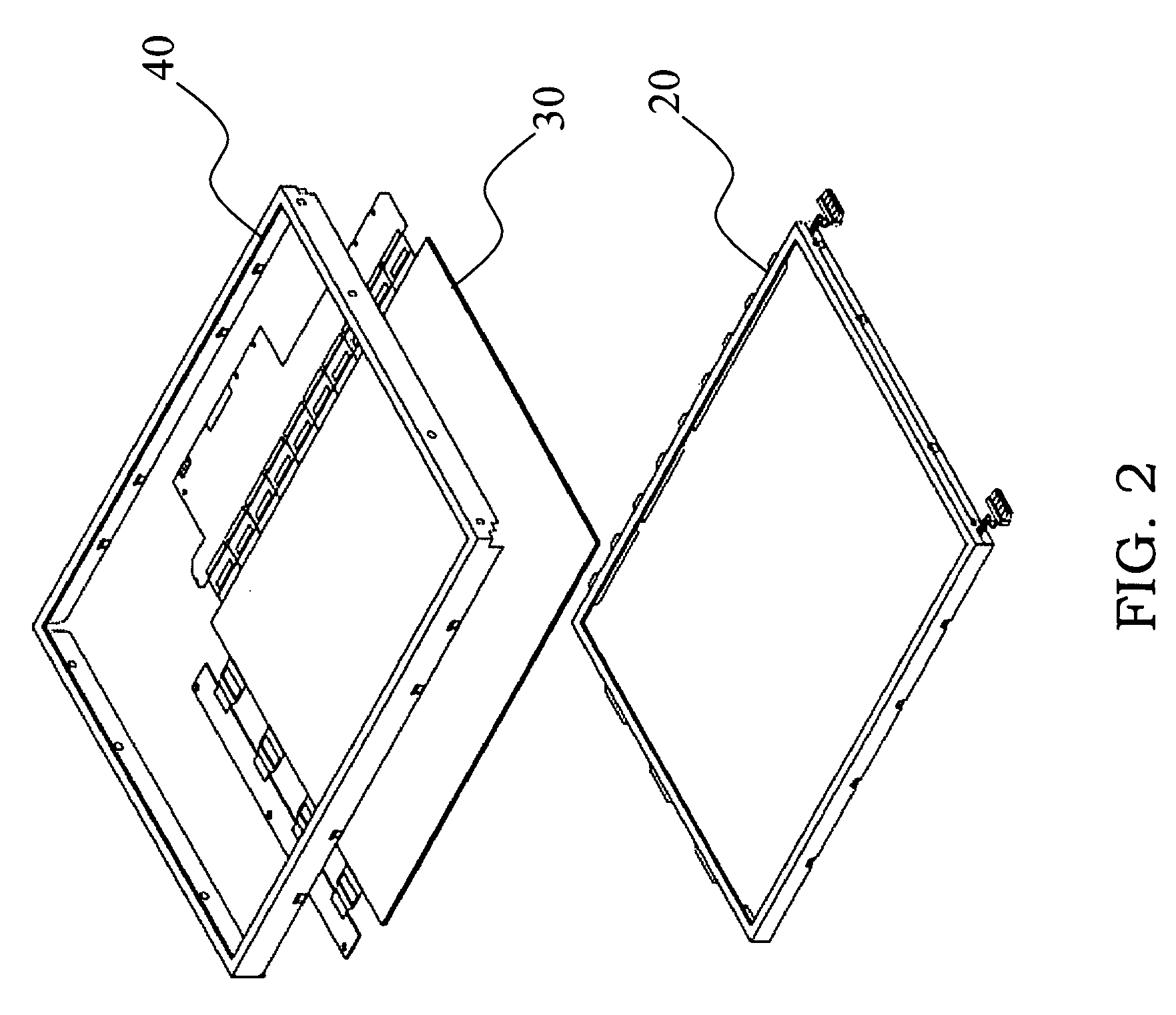
[0017]FIG. 2 is the structure of the FPD in accordance with an embodiment of the present invention. For an FPD, a backlight module 20 provides the FPD with light source needed. A panel module 30 processes the light source to display various images. A fixing frame 40 combines backlight module 20 and panel module 30 and holds them together.

[0018]FIG. 3 is the structure of the backlight module in accordance with the FIG. 2. A light source 21 is positioned at the bottom of the backlight module 20 and a light guide plate 23 is placed on the light source 21. A frame 27 may fix whole assembly of the backlight module 20, wherein an optical film 22 is below the light guide plate 23 and a plurality of optical films 24, 25, and 26 are on the upside of light guide plate 23.

[0019]FIG. 4 is a bottom view of FIG. 3. A frame 222 with geometric pattern is placed on the back of optical film 22, and another side of the frame 222 is toward the inside of the FPD's cover (not shown).

[0020]FIG. 5A is a cr...


PUM


Abstract

The backlight module in the flat panel display (FPD) includes a frame that resides between the backlight module and the cover of FPD display, and has an inclined plane with an angle between the optical film. The inclined plane causes the touching area broader than the parallel plane does, thus it will absorb more stress force and avoid displaying defects in the FPD panel. Using this structure, the pressure transformed from the FPD cover stresses the inclined plane and forces it to contact the FPD's back light module on broader area in reducing the pressure per unit's area.

Description

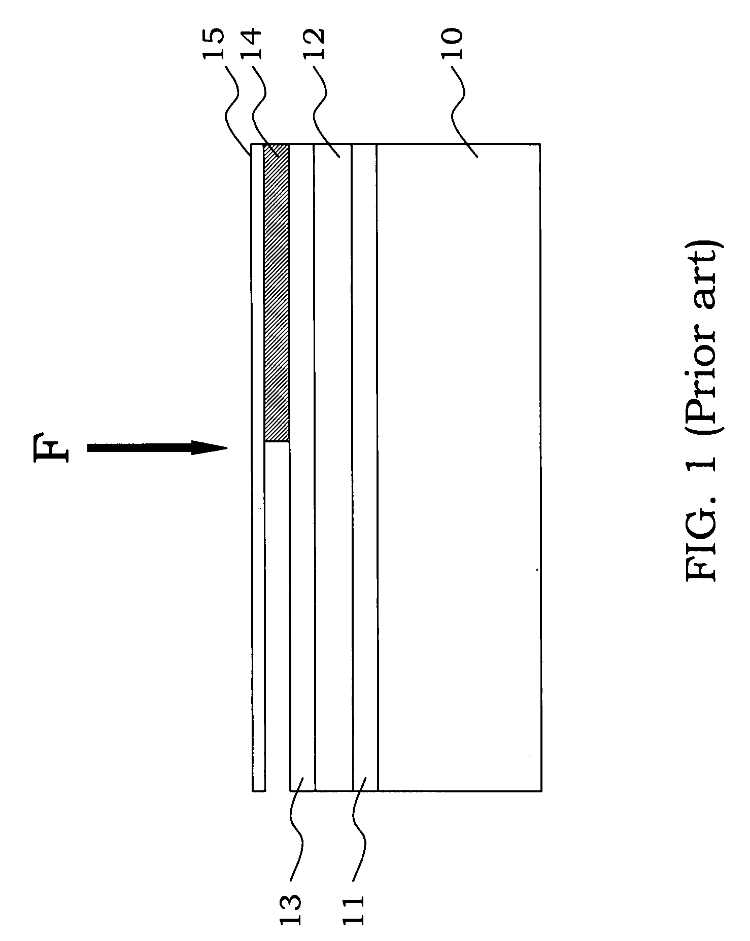
BACKGROUND OF THE INVENTION[0001]1. Field of the Invention[0002]The present invention relates to a backlight module and a flat panel display (FPD), and more especially a backlight module and a flat panel display having a supporting rack for stress dispersion.[0003]2. Background of the Related Art[0004]Generally, in designing the structure of liquid crystal display (LCD), the cover is installed in order to support the whole structure of the back light module in the LCD panel. A frame is disposed between the backlight module and the cover to support the assembly of LCD panel in an integrity way.[0005]In above structure, if imposing pressure on the cover of LCD, the cover will deform in responding to that pressure, and it will continuously bend closely toward the backlight module of the LCD. Consequently, the pressure will be transferred to the back of the backlight module. The FIG. 1 shows a cross-sectional view of frame with the parts of LCD panel. When imposing pressure F on a cover...

Claims


Application Information

Patent Timeline
IPC IPC(8): G02F1/1333
CPCG02B6/0081G02F2201/54G02F1/133608G02B6/0093
Inventor WANG, YAO-TUNGLIAO, KUO-TUNG
Owner CHUNGHWA PICTURE TUBES LTD
Learn More