Stand for holding soldering iron

a technology for holding stands and soldering irons, which is applied in the direction of ohmic-resistance heating, manufacturing tools, and soldering apparatuses, etc., can solve the problems of complex structure of stands, unduly cumbersome processing, and complicated

Inactive Publication Date: 2008-03-20
HON HAI PRECISION IND CO LTD
View PDF14 Cites 18 Cited by
  • Summary
  • Abstract
  • Description
  • Claims
  • Application Information

AI Technical Summary

Problems solved by technology

In conventional uses, structures of stands are usually complex.
This makes the process unduly cumbersome and complicated.

Method used


Image

  • Stand for holding soldering iron
  • Stand for holding soldering iron
  • Stand for holding soldering iron

Examples


Embodiment Construction

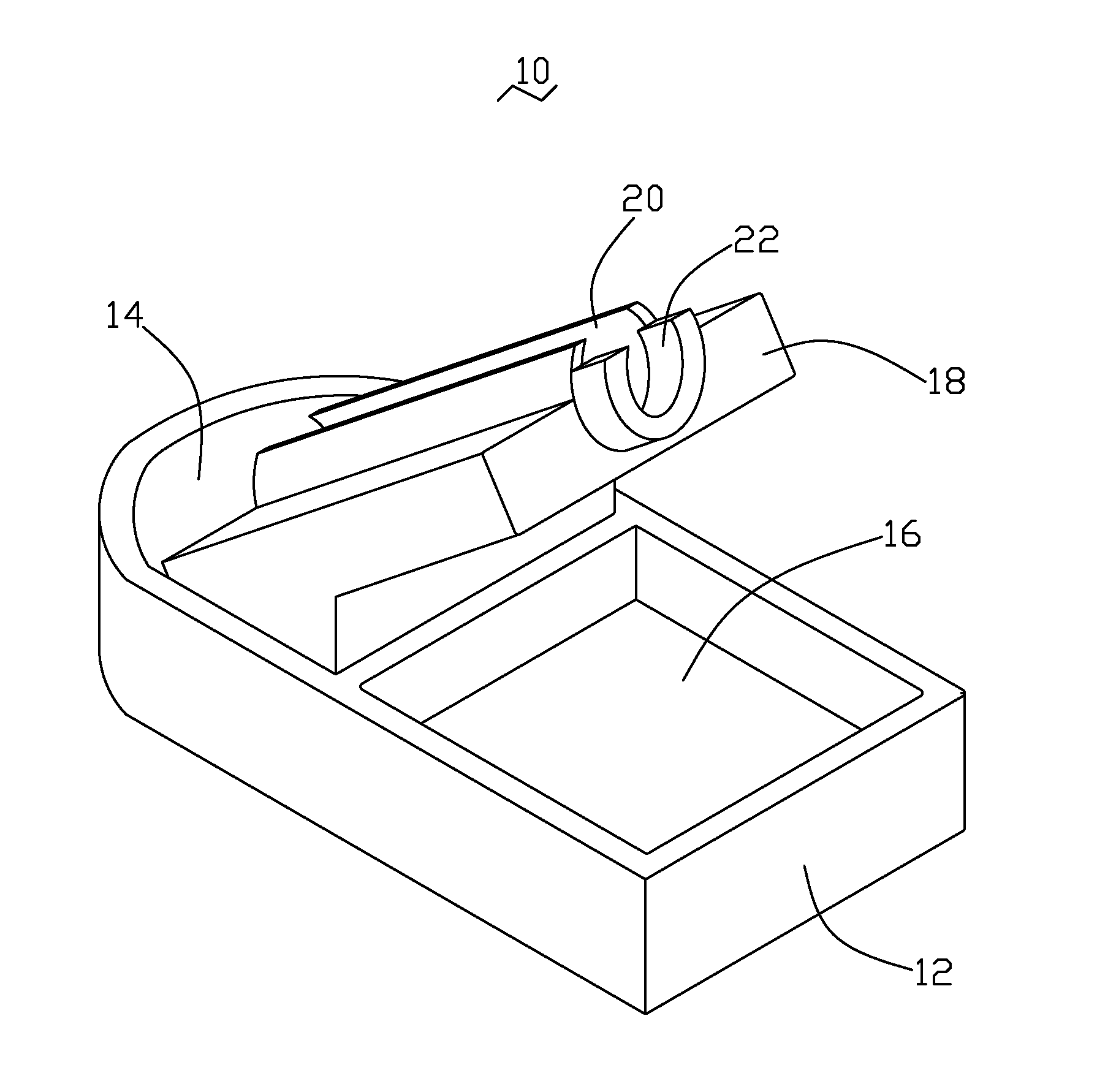
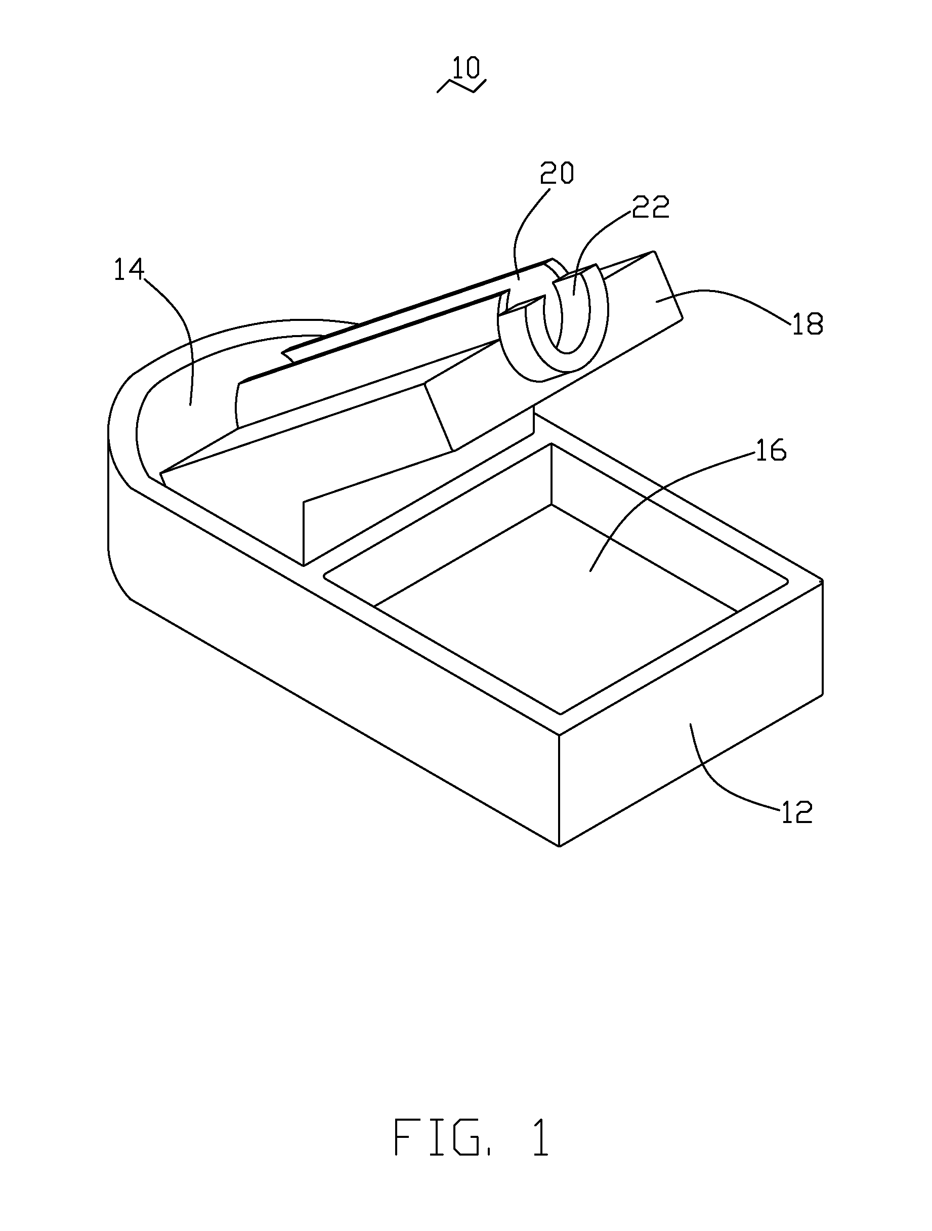
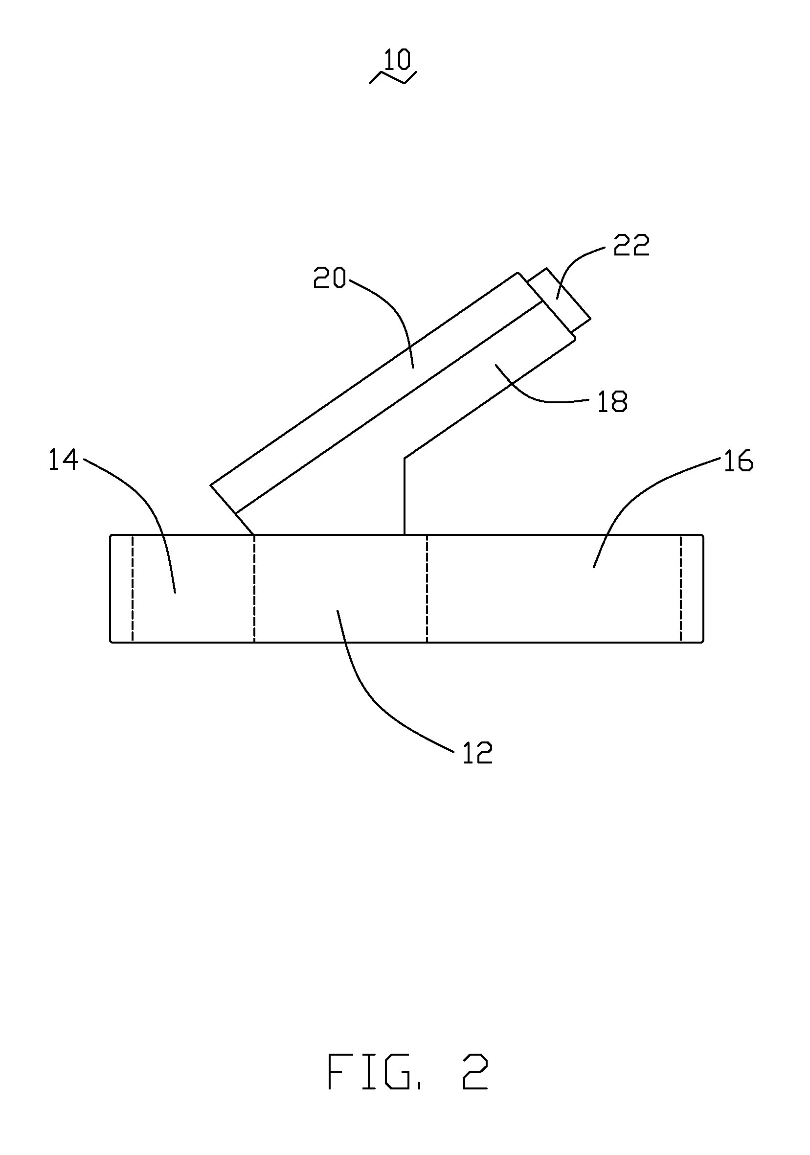
[0012]Referring to FIGS. 1 and 4, a stand 10 for holding a soldering iron 24 therein in accordance with a preferred embodiment of the present invention includes a base 12, and a supporting member 18 extending slantingly and upwardly from the base 12. The soldering iron 24 includes a metal tip 26 and an insulated handle 25.

[0013]The base 12 defines a reservoir 14 in one end thereof configured for receiving solder, and a sponge holder 16 in the other end thereof configured for receiving a sponge. In this embodiment, the sponge holder 16 is rectangular but other shapes may be used as desired. A partition wall separates the reservoir 14 from the sponge holder 16.

[0014]Referring also to FIGS. 2 and 3, the supporting member 18 is integrally and slantingly formed on the base 12, and is disposed between the reservoir 14 and the sponge holder 16, with the upper end hanging above the sponge holder 16.

[0015]The supporting member 18 includes a tube 20 formed lengthwise at an upper slanting surf...


PUM


Abstract

A stand configured for holding a soldering iron therein includes a base, and a supporting member extending slantingly and upwardly from the base. A reservoir is defined in one end of the base for receiving solder therein. A sponge holder sponge holder is defined in another end of the base for receiving a sponge. The supporting member defines a tube for receiving the soldering iron therein. When the soldering iron is holden in the tube of the supporting member, the tip of the soldering iron extends into the solder.

Description

BACKGROUND OF THE INVENTION[0001]1. Field of the Invention[0002]The present invention relates to a stand for holding soldering iron.[0003]2. Description of Related Art[0004]Currently, electronic components are electronically connected to circuit boards via soldering. Owing to susceptibility to oxidation, a tip of a soldering iron should be extended in solder when put away. Then the solder melted away, and finally the tip wiped with a sponge to remove any oxidants adhering to the tip when it's time to solder. However, the iron, the solder, and the sponge are usually put away or stored separately. Accordingly, there is a need for a simple, yet effective soldering iron stand, which reduces or inhibits air circulation about the bit when the iron is on stand-by, and which also provides a more permanent means for holding the soldering iron between uses. In conventional uses, structures of stands are usually complex. This makes the process unduly cumbersome and complicated.[0005]What is ne...

Claims


Application Information

Patent Timeline
Patent Type & Authority Applications(United States)
IPC IPC(8): B23K3/03
CPCB23K3/027
Inventor KUO, SZU-WEI
Owner HON HAI PRECISION IND CO LTD
Why Eureka
Try Eureka