Lever type electrical connector

Active Publication Date: 2008-03-27
MOLEX INC
View PDF20 Cites 12 Cited by
  • Summary
  • Abstract
  • Description
  • Claims
  • Application Information

AI Technical Summary

Benefits of technology

[0008] In principle, an annular shroud is provided to be shifted onto the interfacial seal when the electrical connector (also in partial assembly) is in delivery condition, so that the electrical connector (also in partial assembly) can be shipped and handled without any danger for the interfacial seal. When the lever-type ele

Problems solved by technology

As a matter of fact, seals are very sensitive

Method used


Image

  • Lever type electrical connector
  • Lever type electrical connector
  • Lever type electrical connector

Examples


Example

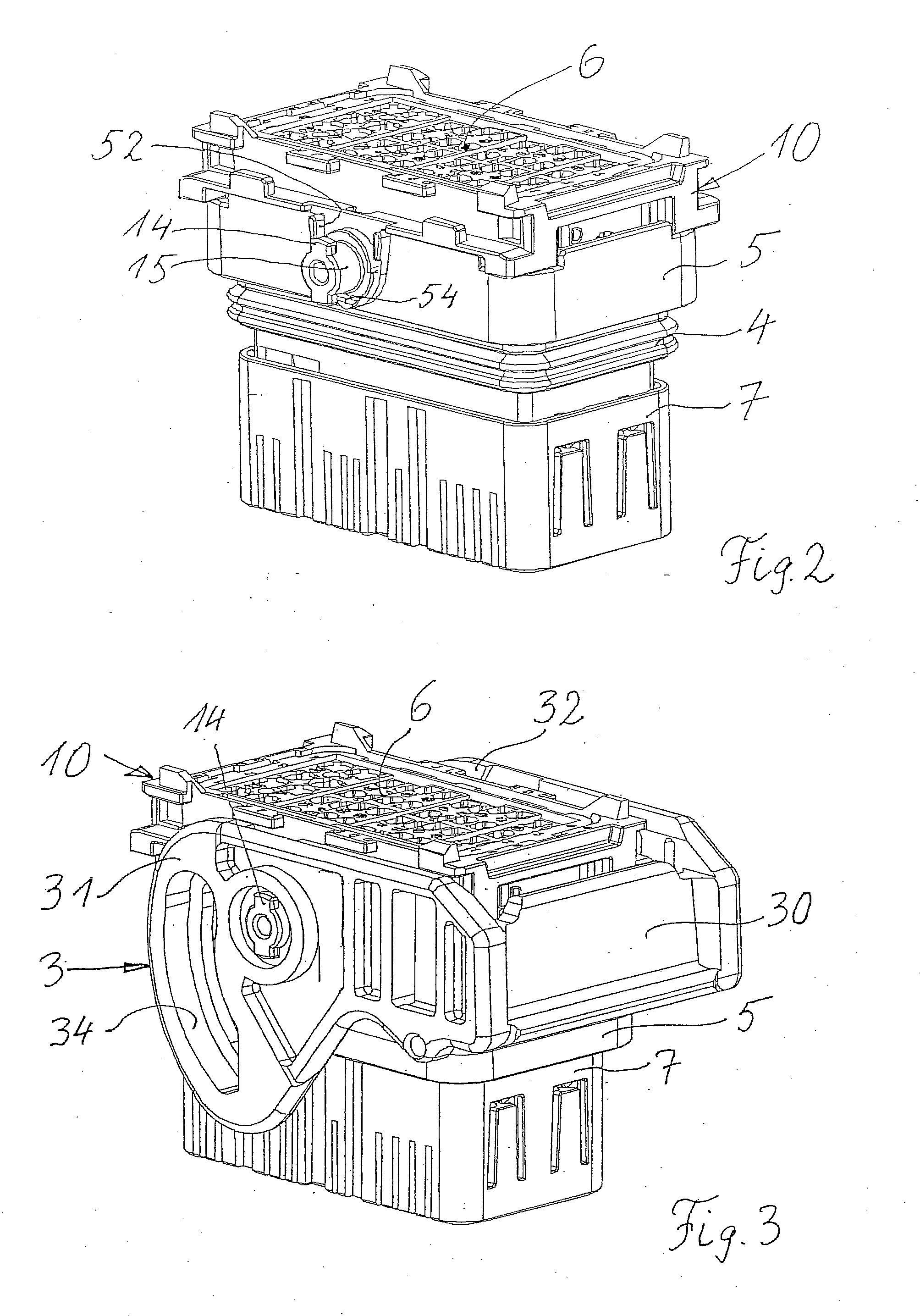
[0024] Referring to FIGS. 4, 5 and 6, a first, lever-type electrical connector 1 is shown in cooperation with a second, complementary electrical connector 2. This second connector 2 has an outer housing member 20 with a cog or pin projection 21 (FIGS. 8-12) on opposite sides of the housing 20, an inner rim zone 22 (FIGS. 5, 6) near the upper end of the housing 20 and a top side 23. Elements which have to do with the invention are a lever 3, an interfacial seal 4 and an annular shroud 5.

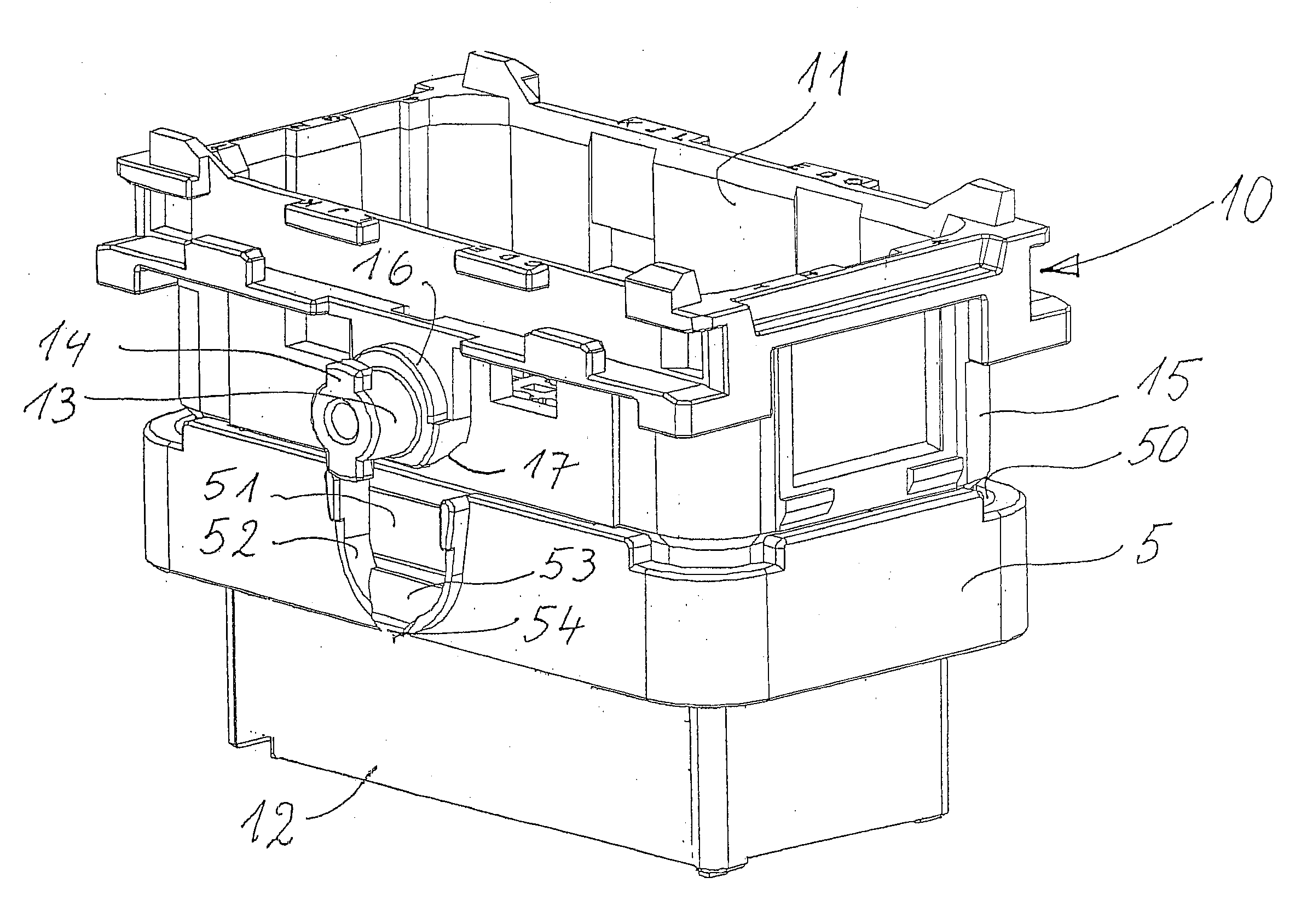
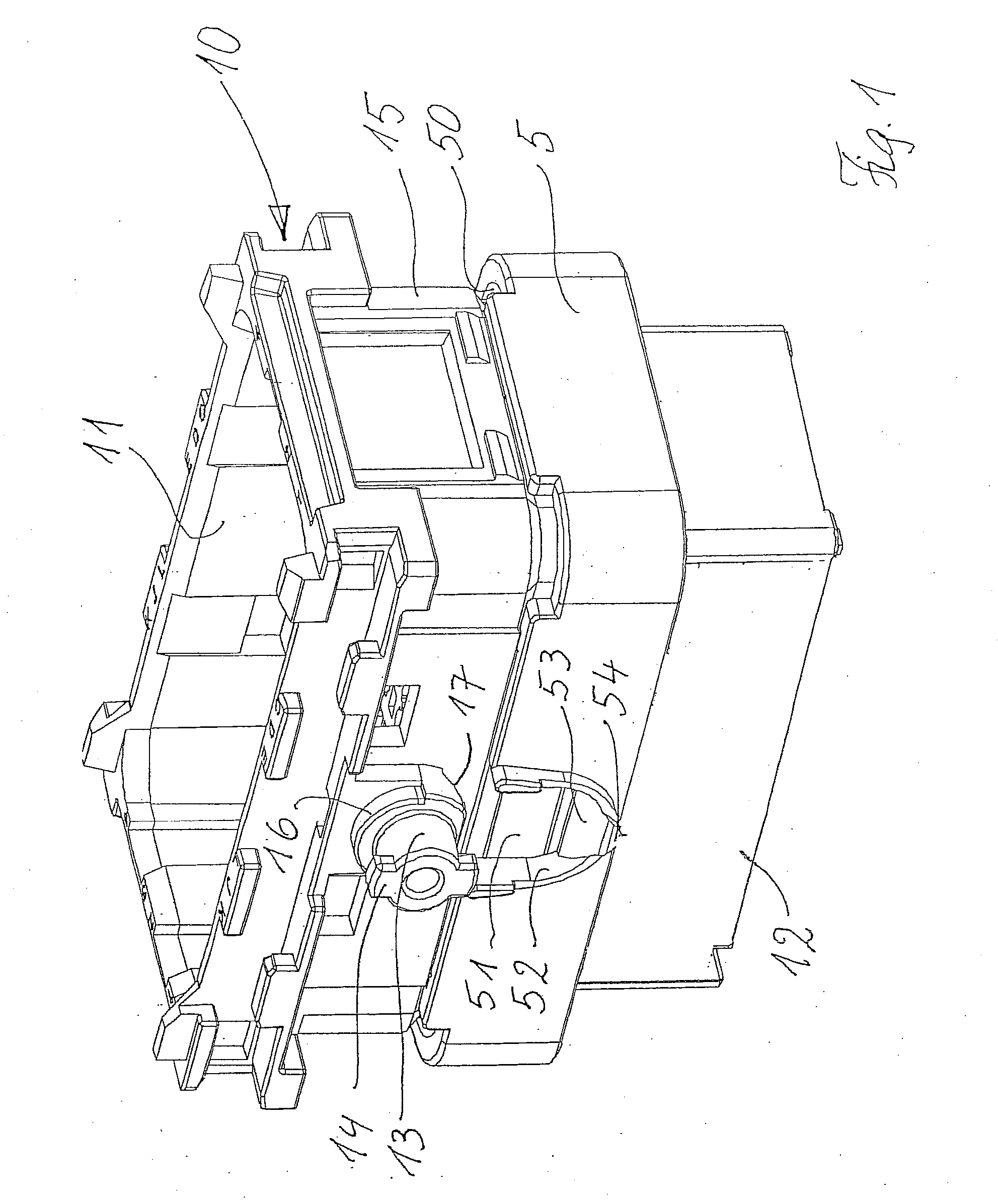
[0025]FIGS. 1 through 4 show the main assembly steps of the lever type electrical connector. The connector 1 comprises a main connector housing 10 which, in this embodiment described, has been molded together with the shroud 5 in one divisible part. Breakable links (not shown) are provided between main connector housing 10 and shroud 5 which are broken when the lever 3 is to be mounted onto the housing 10. It is self-evident that the shroud 5 could have been produced as a separate part. The housing 1...


PUM


Abstract

A lever type electrical connector (1) comprising a connector housing (10) having an annular interfacial seal (4) which extends around the connector housing (10). An annular protecting shroud (5) is arranged surrounding the connector housing (10) without increasing the connector overall dimensions and for being moved in overlapping relationship with said interfacial seal (4) to protect same.

Description

FIELD OF THE INVENTION [0001] The invention relates to an electrical connector (first connector) having a lever for mating and unmating of the first connector with a second complementary electrical connector, and also having an interfacial seal for sealing the gap between the first and the second electrical connectors, when mated. BACKGROUND OF THE INVENTION [0002] A typical lever-type electrical connector comprises a main connector housing having a cavity for taking up body parts in which terminals are received. The main connector housing has outer wall formations wherein the terminal pins are fixed. The wall formations for fixing the terminal pins are covered by an annular body member which is stuck up onto the lower part of the main connector housing. In order to seal the gaps leading to the terminal pins, an annular seal is provided to surround the main connector housing in the region above the terminal pin wall formations. The annular seal is effective as an interfacial seal be...

Claims


Application Information

Patent Timeline
IPC IPC(8): H01R13/62
CPCH01R13/5219H01R13/62955H01R13/62938H01R13/62933
Inventor BOUCHAN, CHRISTOPHEDECHELETTE, PATRICK
Owner MOLEX INC
Why Eureka
Try Eureka