Dental laser treatment hand-piece and system

Inactive Publication Date: 2001-08-07
CERAMOPTEC IND INC
View PDF15 Cites 77 Cited by
  • Summary
  • Abstract
  • Description
  • Claims
  • Application Information

AI Technical Summary

Benefits of technology

The present invention utilizes fluid channels instead of electric wiring to provide power to the treatment device. These fluid channels operate a turbine generator that provides electrical energy to treatment devices. The present invention is compatible with existing pneumatic systems in any dental office and can also be used for a variety of medical applications. The turbine

Problems solved by technology

The general problem with medical or dental devices that employ electrical and/or mechanical tools is that it is difficult to separate the circuits and/or the machinery from parts of the body that don't require treatment.
Any proximity between the patient and the working components that make up the treatment device, increases the risk of harm to the patient.
The shielding materials used in the prior art however, increase the device size and restrict the treatment area.
This restriction in treatment area size often means that a treatment can not be performed as effectively.
This lack of efficiency can also mean that the medical procedure is not cost effective.
Since electrical wiring imposes a multitude of safety restrictions, medical instruments need some alternative energy source.
The drawback to this concept is that optical fibers, especially crystal strands, can often break.
This type of las

Method used


Image

  • Dental laser treatment hand-piece and system
  • Dental laser treatment hand-piece and system
  • Dental laser treatment hand-piece and system

Examples


Example

EXAMPLE 1

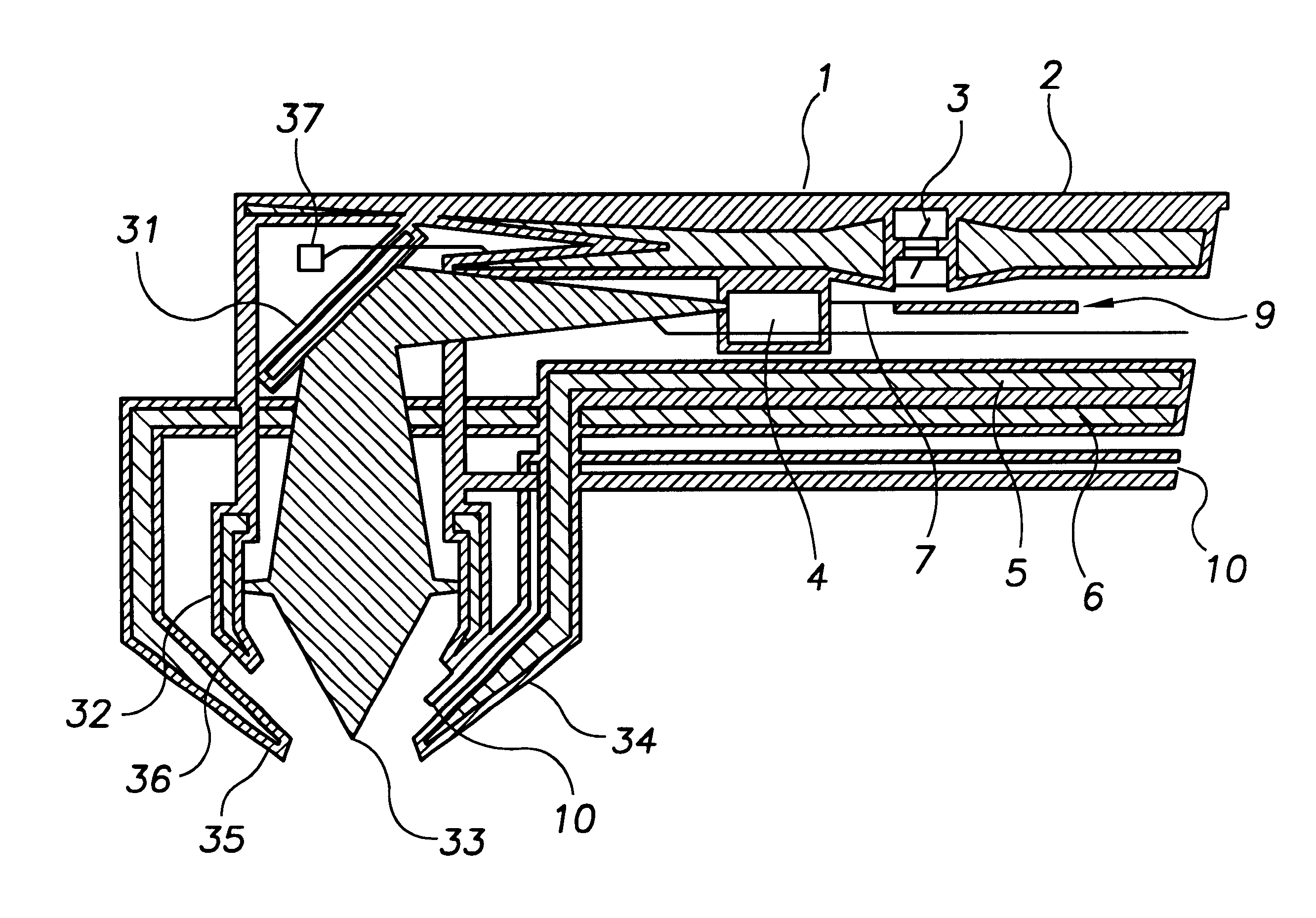
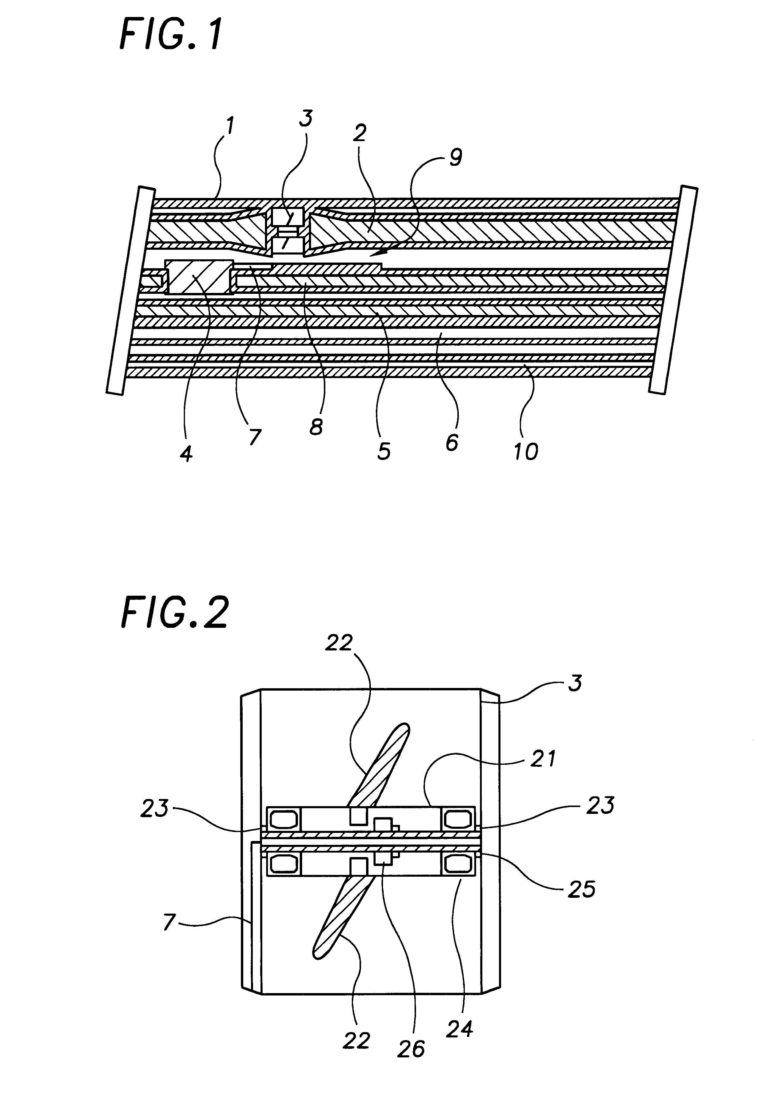
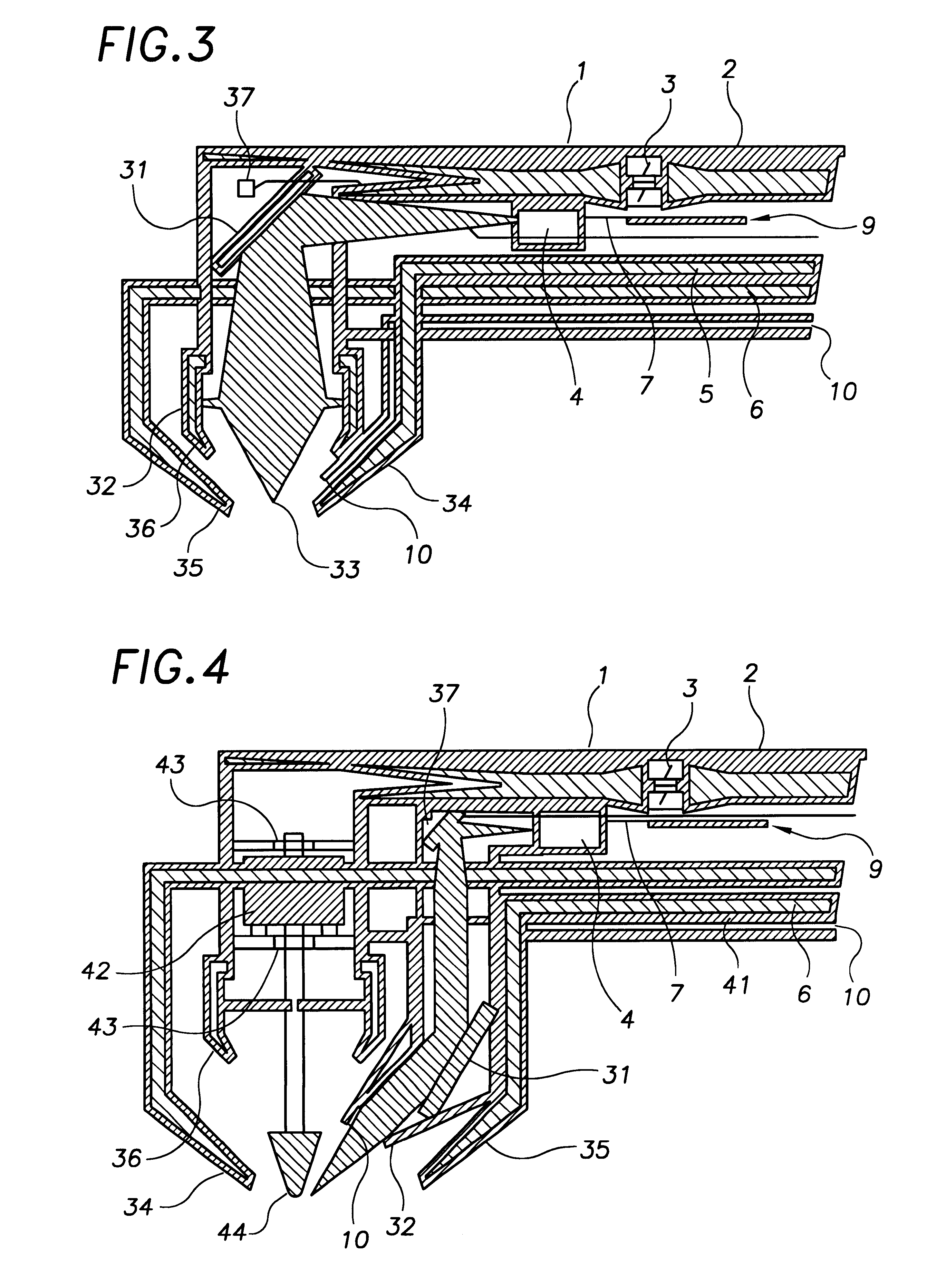
A preferred embodiment of a hand-piece for dental applications is illustrated in FIG. 3. This particular embodiment can be employed for any general laser surgery or for dental tissue treatment. The hand-piece contains micro turbine engine 3, power fluid supply channel 2 to drive micro turbine generator 3, additional fluid supply channel 8 to functional device 4, secondary supply channel 5 and aspiration vacuum channel 6. Power fluid supply channel 2 terminates / empties near treatment zone 33 after passing micro turbine generator 3. The fluid itself can additionally serve to cool the treatment zone.

In this embodiment, functional device 4 is a semiconductor diode laser, which can produce radiation in a wavelength range of 400 to 3000 nm and an output power of up to 50 W in either cw or pulsed mode. The embodiment also includes power-measuring device 37, which can be enclosed in several ways. It is placed in such a way that it can detect the radiation that is back scattered fro...

Example

EXAMPLE 2

FIG. 4 illustrates a hand-piece that combines a turbine generator driven laser and a conventional turbine drill. Turbine drill 42 is driven by secondary supply channel 5. Drill axis 43 is perpendicular to the treatment zone. Drill head 44 is placed at the end of turbine axis 43. Drill head 44 can be changed to perform different treatments apart from basic drilling. Preferably, a dense fluid is used to drive the turbine drill and allow heat generated by internal friction to dissipate. Sealed outer shaft 1 contains power fluid supply channel 2 and micro-turbine generator 3. Once power fluid supply channel 2 has passed through micro turbine generator 3, the fluid is delivered to the treatment zone. Functional device 4 is a laser in this embodiment. Device 4 assists drilling by pre-heating the dental material. This pre-heating reduces the amount of larger particles that break off while drilling and increases accuracy. Since fewer large particles break off while drilling, only t...

Example

EXAMPLE 3

In the embodiment depicted in FIG. 5, the laser radiation does not directly propagate via optics to the treatment zone, but instead is coupled to a light guide. Light guide 51 may be a flexible optical fiber or a stiff wave-guide since the distance is small. Light guide 51 directs light to focusing optics 32. Focusing optics 32 project the radiation from light guide 51's distal end to treatment zone 33. Focusing optics 32 ensure adequate irradiation of the diseased areas. In the prior art a light guide must run all the way from an exterior control unit to the hand-piece. The present invention has several advantages over the prior art. Since the light source is contained within the hand-piece, the light guide does not need to be flexible. Furthermore, since the length is significantly shorter, there is a significant reduction in the risk of malfunction.

In another embodiment that is a variation of this example, it is possible to use multiple micro-turbine engines to drive mul...


PUM


Abstract

A handpiece is presented which utilizes fluid channels instead of electric wiring to provide power to a treatment device. These fluid channels operate a micro-turbine generator that provides electrical energy to treatment devices. Each micro-turbine generator generates electrical energy for powering at least one electricity consuming functional device; wherein said electricity consuming functional device is selected from the group; a compact laser, an electromechanical dental drill, an ultrasound generator, a microwave generator and, an activator for treatment chemicals. In particular this device provides energy to a dental hand-piece without the need for electrical wiring or optics between the hand-piece and the control apparatus. One or more fluid channels permit fluids to flow between the control apparatus and the hand-piece. This flow of fluid operates the micro-turbine, which in turn produces energy to operate a medical/dental device. The fluid channels can also be used to deliver substances in conjunction with the medical device use. The hand-piece of this apparatus can be manufactured for a specific medical/dental procedure, or the apparatus can be made compatible/interchangeable with existing hand-pieces and control apparatus. This micro-turbine energy system provides the power necessary to operate many state of the art devices. For example, the energy produced can be used to operate a laser used for various dental applications such as drilling, pre-heating of the drill area, or activation of PDT substances.

Description

BACKGROUND OF THE INVENTION1. Field of the InventionThe present invention relates to small sealed handheld laser systems, which fulfill all clinical use requirements and which can be operated simply. In particular, this invention refers to laser hand-pieces for use in the dental field.2. Invention Disclosure StatementThe general problem with medical or dental devices that employ electrical and / or mechanical tools is that it is difficult to separate the circuits and / or the machinery from parts of the body that don't require treatment. Any proximity between the patient and the working components that make up the treatment device, increases the risk of harm to the patient. The shielding materials used in the prior art however, increase the device size and restrict the treatment area. This restriction in treatment area size often means that a treatment can not be performed as effectively. This lack of efficiency can also mean that the medical procedure is not cost effective.A typical ha...

Claims


Application Information

Patent Timeline
IPC IPC(8): A61C1/00A61C1/05A61C3/025A61C19/06
CPCA61C1/0046A61C1/0061A61C3/025A61C19/063A61C1/05
Inventor NEUBERGER, WOLFGANGQUADE, MICHAEL
Owner CERAMOPTEC IND INC
Why Eureka
Try Eureka