Methods for ablation with radiant energy

a technology of radiant energy and ablation chamber, which is applied in the field of ablation instruments, can solve the problems of ineffective quivering, inability to achieve the effect of quivering, and inability to efficiently quiver, and achieves the effect of less risk, less time, and rapid and effective photoablation

Inactive Publication Date: 2006-11-09
CARDIOFOCUS INC
View PDF99 Cites 95 Cited by
  • Summary
  • Abstract
  • Description
  • Claims
  • Application Information

AI Technical Summary

Benefits of technology

[0020] The instruments are especially useful in percutaneous access cardiac surgery for rapid and efficient creation of curvilinear lesions to serve as conduction blocks. The instruments are designed to create lesions in the atrial tissue in order to electrically decouple tissue segments on opposite sides of the lesion while presenting low profiles during percutaneous access and retraction. The instruments of the present invention permit the formation of continuous lesions in the atrial wall tissue of the heart, such that the continuous lesion can surround a organ structure, such as a pulmonary vein, without involving the structure itself.
[0024] In a further aspect of the invention, percutaneous instruments are disclosed that can achieve rapid and effective photoablation through the use of tissue-penetrating radiant energy. It has been discovered that radiant energy, e.g., projected electromagnetic radiation or ultrasound, can create lesions in less time and with less risk of the adverse types of surface tissue destruction commonly associated with prior art approaches. Unlike instruments that rely on thermal conduction or resistive heating, controlled penetrating radiant energy can be used to simultaneously deposit energy throughout the full thickness of a target tissue, such as a heart wall, even when the heart is filled with blood. Radiant energy can also produce better defined and more uniform lesions.
[0025] The use of radiant energy, in conjunction with catheter structures that are substantially transparent to such radiation at the therapeutic wavelengths, is particularly advantageous in affording greater freedom in selecting the location of the lesion, e.g., the site is no longer limited to the pulmonary vein itself. Because the energy can be projected onto the tissue, a ring-like lesion can be formed in atrial tissue at a distance from the vein, thereby reducing the potential for stenosis and / or other damage to the vein itself.
[0029] In the case of radiant light, the energy delivering element can include a light transmitting optical fiber adapted to receive ablative radiation from a radiation source and a light emitting tip at a distal end of the fiber for emitting radiation. The light delivering element can be slidably disposed within an inner lumen of the catheter body and the instrument can further include a translatory mechanism for disposing the tip of the light delivering element at one or more of a plurality of locations with the catheter. Moreover, by moving the energy-projecting tip assembly within the catheter, the diameter of the projected ring of energy can be readily varied, thereby permitting the clinician control over the location (and size) of the lesion to be formed.
[0031] It can also be desirable to employ an “ablative fluid” outside of the instrument (e.g., between the balloon and the target region) to ensure efficient transmission of the radiant energy when the instrument is deployed. An “ablative fluid” in this context is any fluid that can serve as a conductor of the radiant energy. This fluid can be a physiologically compatible fluid, such as saline, or any other non-toxic aqueous fluid that is substantially transparent to the radiation. In one preferred embodiment, the fluid is released via one or more exit ports in the housing and flows between the projection balloon and the surrounding tissue, thereby filling any gaps where the balloon does not contact the tissue. The fluid can also serve an irrigation function by displacing any blood within the path of the radiant energy, which could otherwise interfere because of the highly absorptive nature of blood with respect to radiant light energy.
[0035] The coaxial catheter instruments disclosed herein are of particular use in percutaneous applications whereby a balloon catheter with an ablative light or ultrasound projecting assembly can be disposed within a patient's heart. In another aspect of the invention, dual, coaxial balloon structures are disclosed, having both a projection balloon and an anchoring balloon to assist in the properly disposition of the instrument.

Problems solved by technology

The regular pumping function of the atria is replaced by a disorganized, ineffective quivering as a result of chaotic conduction of electrical signals through the upper chambers of the heart.
Devices that rely upon resistive or conductive heat transfer can be prone to serious post-operative complications.
To achieve this, the temperature at the contact surface will typically be raised to greater than 100° C. In this temperature regime, there is a substantial risk of tissue destruction (e.g., due to water vaporization micro-explosions or due to carbonization).
Charring of the surface of the heart tissue, in particular, can lead to the creation of blood clots on the surface and post-operative complications, including stroke.
When the light energy is delivered in the form of a focused spot, the process is inherently time consuming because of the need to expose numerous spots to form a continuous linear or curved lesion.
In addition, existing instruments for cardiac ablation also suffer from a variety of design limitations.
The shape of the heart muscle adds to the difficulty in accessing cardiac structures, such as the pulmonary veins on the anterior surface of the heart.
Moreover, because the lesion is formed by an ablation element carried on the surface of the balloon element, the balloon shape inherently limits the locations where a lesion can be formed, i.e., the lesion must be formed at least partially within the pulmonary vein.
With the Swartz et al. device, like the Lesh device, the region where tissue ablation can occur is limited by the design.
Ablation within the pulmonary vein can result in complications.
Overtreatment deep within a vein can result in stenosis (closure of the vein itself), necrosis or other structural damage, any of which can necessitate immediate open chest surgery.
A major limitation in the prior art percutaneous designs is the lack of site selectability.
Practically speaking, each prior art percutaneous instrument is inherently limited by its design to forming an ablative lesion at one and only one location.
It is not possible to form the lesion at another location because the heating element must contact the target tissue.
Another major limitation in prior art percutaneous designs is their inability to accommodate the actual and quite varied geometry of the heart.
When the expandable, contact heating devices of the prior art encounter irregularly-shaped ostia, the result can be an incompletely formed (non-circumferential) lesion.
Moreover, the prior art devices typically can not determine whether continuous circumferential contact has been achieved before heating commences.

Method used


Image

  • Methods for ablation with radiant energy
  • Methods for ablation with radiant energy
  • Methods for ablation with radiant energy

Examples


Embodiment Construction

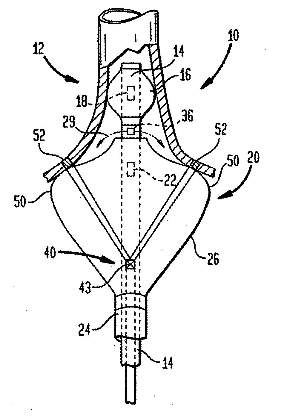
[0069]FIG. 1 provides a schematic, cross-sectional view of a coaxial catheter ablation instrument 10 according to the invention, including a first, inner catheter 12 having an elongate body 14 and an anchor balloon 16, inflatable via one or more ports 18. A fluid for inflating the anchor balloon can be delivered through a passageway (not shown) within the elongate body or via one or more of the lumens of the device, as discussed in more detail below. The device can further include a second, coaxial, outer catheter 20 having an elongate body 24 and a projection balloon 26 inflatable via one or more ports 22. The instrument is preferably designed such that upon anchorage of the anchor balloon 16 within the heart (e.g., within a pulmonary vein), the projection balloon can be inflated such a shoulder portion 50 of the balloon 26 will be urged into close proximity with a target region 52 of cardiac tissue (e.g. an annular region of the atrial heart wall surrounding the ostium of a pulmon...


PUM

PropertyMeasurementUnit
wavelengthaaaaaaaaaa
temperatureaaaaaaaaaa

Abstract

Ablation methods and instruments are disclosed for creating lesions in tissue, especially cardiac tissue for treatment of arrhythmias and the like. Percutaneous ablation instruments in the form of coaxial catheter bodies are disclosed having at least one central lumen therein and having one or more balloon structures at the distal end region of the instrument. The instruments include an energy emitting element which is independently positionable within the lumen of the instrument and adapted to project radiant energy through a transmissive region of a projection balloon to a target tissue site. The instrument can optionally include at least one expandable anchor balloon disposed about, or incorporated into an inner catheter body designed to be slid over a guidewire. This anchor balloon can serve to position the device within a lumen, such as a pulmonary vein. A projection balloon structure is also disclosed that can be slid over the first (anchor balloon) catheter body and inflated within the heart, to define a staging from which to project radiant energy. An ablative fluid can also be employed outside of the instrument (e.g., between the balloon and the target region) to ensure efficient transmission of the radiant energy when the instrument is deployed. In another aspect of the invention, generally applicable to a wide range of cardiac ablation instruments, mechanisms are disclosed for determining whether the instrument has been properly seated within the heart, e.g., whether the device is in contact with a pulmonary vein and / or the atrial surface, in order to form a lesion by heating, cooling or projecting energy. This contact-sensing feature can be implemented by an illumination source situated within the instrument and an optical detector that monitors the level of reflected light. Measurements of the reflected light (or wavelengths of the reflected light) can thus be used to determine whether contact has been achieved and whether such contact is continuous over a desired ablation path.

Description

CROSS-REFERENCE TO RELATED APPLICATIONS [0001] This application is a continuation-in part of U.S. patent application Ser. No. 09 / 924,393, filed on Aug. 7, 2001, which is a continuation-in-part of U.S. patent application Ser. No. 09 / 390,964, filed Sep. 7, 1999, now U.S. Pat. No. 6,270,492 issued Aug. 7, 2001, which is a continuation-in-part of U.S. patent application Ser. No. 08 / 991,130, filed Dec. 16, 1997, now U.S. Pat. No. 5,947,595 issued Sep. 7, 1999, which is a continuation-in-part of U.S. patent application Ser. No. 08 / 827,631, filed Apr. 10, 1997, now U.S. Pat. No. 5,908,415 issued Jun. 1, 1999, which is a continuation of U.S. patent application Ser. No. 08 / 303,605, filed Sep. 9, 1994, abandoned. [0002] This application is also a continuation-in-part of U.S. patent application Ser. No. 09 / 616,275 filed Jul. 14, 2000, which is a continuation-in-part of U.S. patent application Ser. No. 09 / 602,420 filed Jun. 23, 2000, which is a continuation-in-part of U.S. patent application Se...

Claims


Application Information

Patent Timeline
Patent Type & Authority Applications(United States)
IPC IPC(8): A61B18/18A61B17/00A61B18/00A61B18/22A61B18/24A61B19/00A61F2/958A61L2/10A61L29/08A61N5/06A61N7/02
CPCA61B18/24A61B18/245A61B2017/00057A61B2017/00061A61B2018/0097A61B2018/2261A61B2018/2266A61N7/02A61B2018/2272A61B2019/465A61L2/10A61L29/085C08L27/12A61B2090/065
Inventor ARNOLD, JEFFREY M.SINOFSKY, EDWARD L.BAXTER, LINCOLN S.FARR, NORMAN E.
Owner CARDIOFOCUS INC
Why Eureka
Try Eureka