Methods and devices for delivering ablative energy

a technology of ablative energy and ablation device, which is applied in the field of medical therapies, can solve the problems of ineffective quivering, inability to restore normal cardiac hemodynamics, and inability to achieve normal cardiac hemodynamics, and achieve the effect of rapid and efficient creation of curvilinear lesions

Inactive Publication Date: 2005-12-29
EDWARDS LIFESCIENCES CORP
View PDF13 Cites 139 Cited by
  • Summary
  • Abstract
  • Description
  • Claims
  • Application Information

AI Technical Summary

Benefits of technology

[0013] The present invention provides surgical ablation instrument systems for creating lesions in tissue, especially cardiac tissue for treatment of arrhythmias and other cardiac conditions. The hand held instruments are especially useful in open chest or port access cardiac surgery for rapid and efficient creation of curvilinear lesions to serve as conduction blocks. The instruments can be applied to form either endocardial or epicardial ablations, and are designed to create lesions in the atrial tissue in order to electrically decouple tissue segments on opposite sides of the lesion.
[0016] In another aspect of the invention, the housing can include a profile that provides for longitudinal flexibility as well as torsional strength. In one embodiment, the housing includes a shaped inner lumen for containing a complementarily shaped light delivering element. The specific geometries of the lumen and element are such that twisting or rotation of the light delivering element within the inner lumen is prevented, and the orientation of the light delivering element with respect to the housing is ensured. In another embodiment, the housing can include reinforcement such as shape memory wire or polymeric supports to prevent the housing from twisting when positioned on tortuous anatomical surfaces.
[0017] In one aspect of the invention, hand-held and percutaneous instruments are disclosed that can achieve rapid and effective photoablation through the use of penetrating radiation, especially distributed radiant energy. It has been discovered that radiant energy, e.g., diffuse infrared radiation, can create lesions in less time and with less risk of the adverse types of tissue destruction commonly associated with prior art approaches. Unlike instruments that rely on thermal conduction or resistive heating, controlled penetrating radiant energy can be used to simultaneously deposit energy throughout the full thickness of a target tissue, such as a heart wall, even when the heart is filled with blood. Distributed radiant energy can also produce better defined and more uniform lesions.
[0022] In another embodiment, the instrument can include an inflatable elongate balloon that resides within the housing along with the light delivering element. An inflation controller in communication with the balloon and an inflation source, e.g., an air, gas or fluid pump, can be provided to enable the selective inflation of the balloon. Upon inflation, the balloon urges against the light delivering element and effects the angular orientation of the element with respect to the longitudinal axis of the housing. This allows the surgeon to change the angle of the light delivering element by controlling the inflation of the balloon, and consequently the energy emitting pathway along the length of the light delivering element.
[0034] In yet another aspect, a percutaneous cardiac ablation instrument in the form of a balloon catheter with an ablative light projecting assembly is provided. The balloon catheter instrument can include at least one expandable membrane disposed about a housing. This membrane is generally or substantially sealed and serves as a balloon to position the device within a lumen. The balloon structure, when filled with fluid, expands and is engaged in contact with the tissue. The expanded balloon thus defines a staging from which to project ablative radiation in accordance with the invention. The instrument can also include an irrigation mechanism for delivery of fluid at the treatment site. In one embodiment, irrigation is provided by a sheath, partially disposed about the occluding inner balloon, and provides irrigation at a treatment site (e.g. so that blood can be cleared from an ablation site). The entire structure can be deflated by applying a vacuum which removes the fluid from the inner balloon. Once fully deflated, the housing can be easily removed from the body lumen.

Problems solved by technology

The regular pumping function of the atria is replaced by a disorganized, ineffective quivering as a result of chaotic conduction of electrical signals through the upper chambers of the heart.
However, these procedures have for the most part failed to restore normal cardiac hemodynamics, or alleviate the patient's vulnerability to thromboembolism because the atria are allowed to continue to fibrillate.
Ablation procedures are often performed during coronary artery bypass and mitral valve replacement operations because of a heightened risk of arrhythmias in such patients and the opportunity that such surgery presents for direct access to the heart.
These devices, however, are not without their drawbacks.
The total length of time to form the necessary lesions can be excessive.
This is particularly problematic for procedures that are performed upon a “beating heart” patient.
Moreover, devices that rely upon resistive or conductive heat transfer can be prone to serious post-operative complications.
To achieve this, the contact surface will typically be raised to at least 80° C. Charring of the surface of the heart tissue can lead to the creation of blood clots on the surface which can lead to post-operative complications, including stroke.
When the light energy is delivered in the form of a focused spot, the process is inherently time consuming because of the need to expose numerous spots to form a continuous linear or curved lesion.
In addition, existing instruments for cardiac ablation also suffer from a variety of design limitations.
The shape of the heart muscle adds to the difficulty in accessing cardiac structures, such as the pulmonary veins which are located on the posterior surface of the heart.
Further, the presence of epicardial fat limits the depth of ablative penetration for many ablative energy sources.

Method used


Image

  • Methods and devices for delivering ablative energy
  • Methods and devices for delivering ablative energy
  • Methods and devices for delivering ablative energy

Examples


Embodiment Construction

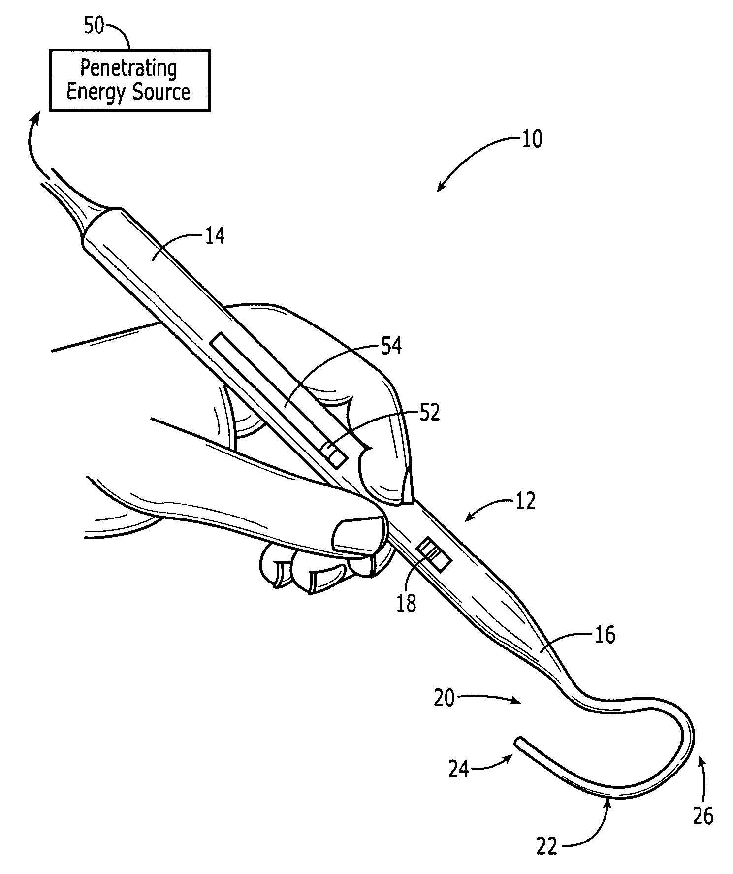
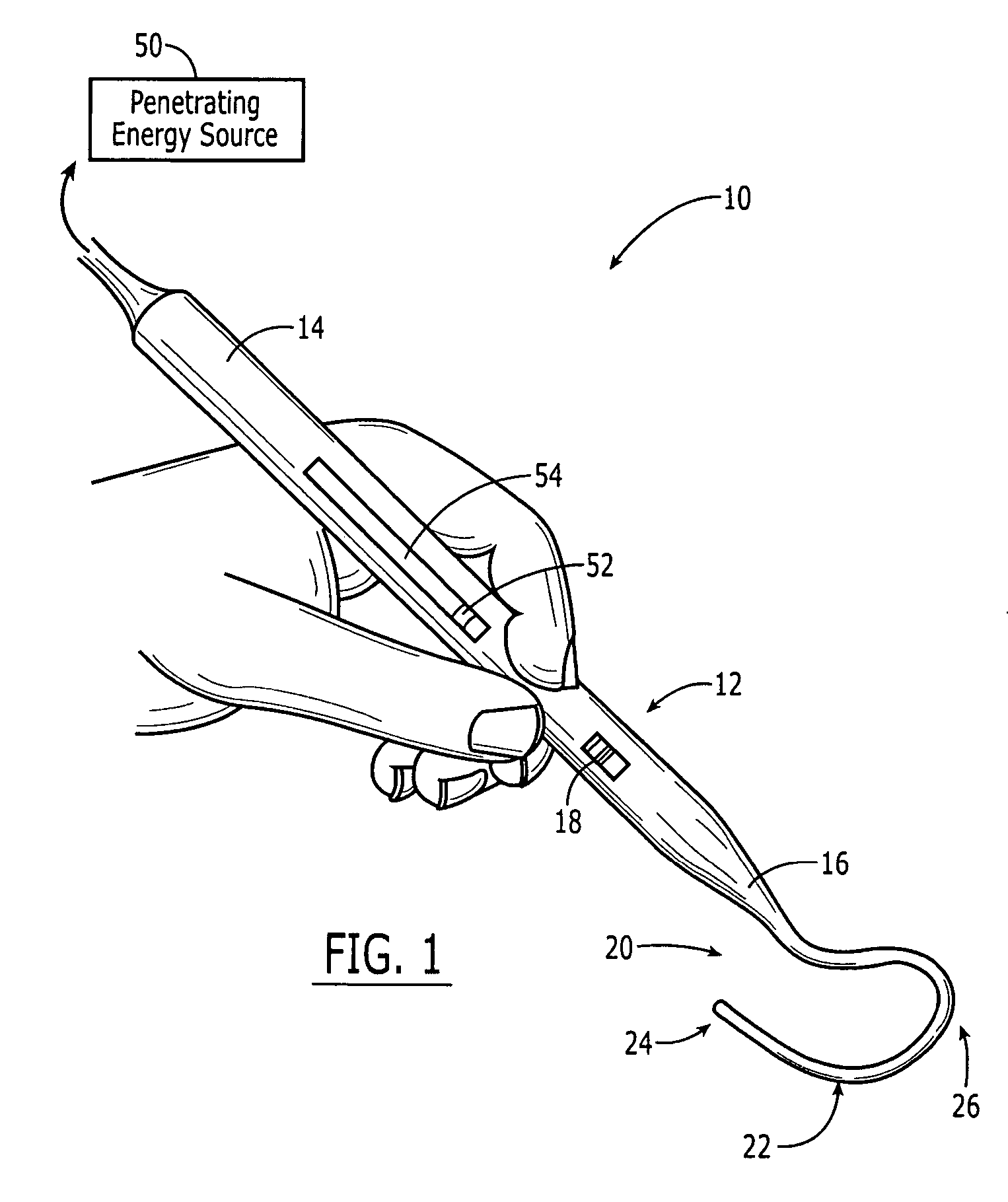
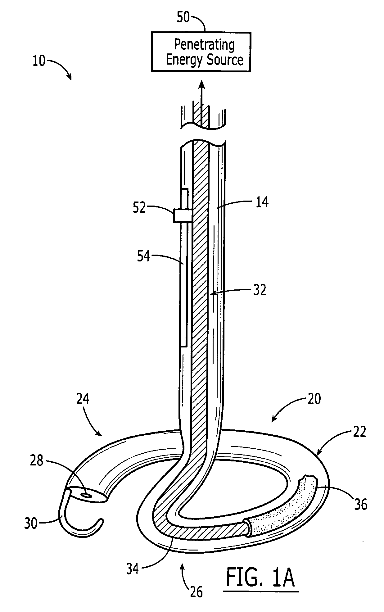
[0100] The present invention provides hand held surgical ablation instruments that are useful for treating patients with cardiac conditions such as, for example, atrial arrhythmia. Turning now to the drawings and particularly to FIG. 1, an exemplary embodiment of a hand held cardiac ablation instrument 10 in accordance with the present invention is shown. Ablation instrument 10 generally includes a handle 12 having a proximal end 14 and a distal end 16, an ablation element 20 mated to or extending distally from the distal end 16 of the handle 12, and a penetrating energy source 50. The energy source 50 can be, for example, a laser source of radiation, e.g., coherent light, which can be efficiently and uniformly distributed to the target site while avoiding harm or damage to surrounding tissue. In use, the instrument 10 can be applied either endocardially or epicardially, and is effective to uniformly irradiate a target ablation site.

[0101] The handle 12 of the ablation instrument 1...


PUM


Abstract

Ablation instruments and methods are disclosed for ablating diseased tissue such as cardiac tissue. The ablation device can remotely apply ablative energy to biological tissue and comprises a flexible elongate member having a proximal end, a distal end and a longitudinal lumen extending therebetween. An energy emitting element is disposed within the longitudinal lumen of the flexible elongate member. The energy emitting element has a proximal end and a distal end for emitting energy along at least a portion of its length. The device is configured to emit a variable amount of energy along a length of the flexible elongate member. The method includes introducing the flexible elongate member into a predetermined tissue site to ablate a target tissue. The target tissue is ablated, coagulated or photochemically modulated without damaging surrounding tissue.

Description

CROSS-REFERENCE TO RELATED APPLICATIONS [0001] The pending application claims priority to U.S. Provisional Application No. 60 / 578,021 filed on Jun. 7, 2004 and to U.S. Provisional Application No. 60 / 672,919 filed on Apr. 18, 2005, which are hereby incorporated by reference in their entirety.FIELD OF THE INVENTION [0002] The present invention relates to ablation devices for medical therapies. In particular, the present invention relates to ablation instrument systems that use energy to ablate internal bodily tissues, and methods for using such systems for the treatment of diseases. Even more particularly, the systems and methods of the present invention can be used, for example, in the treatment of cardiac conditions such as cardiac arrhythmias. BACKGROUND OF THE INVENTION [0003] Cardiac arrhythmias, e.g., fibrillation, are irregularities in the normal beating pattern of the heart and can originate in either the atria or the ventricles. For example, atrial fibrillation is a form of a...

Claims


Application Information

Patent Timeline
Patent Type & Authority Applications(United States)
IPC IPC(8): A61B17/00A61B18/00A61B18/14A61B18/20A61B18/22
CPCA61B18/14A61B18/22A61B2018/2272A61B2018/00196A61B2018/2261A61B2017/00243A61B2018/00577
Inventor NIEMAN, TIMDANG, NINH HUUPRUITT, TAZIWARD, JIM L.BULMAN, ERIKWILLIAMS, MATHEW R.MURPHY, JOHN
Owner EDWARDS LIFESCIENCES CORP
Why Eureka
Try Eureka