Stent with soluble bladder retention member

Active Publication Date: 2008-03-27
BOSTON SCI SCIMED INC
View PDF31 Cites 16 Cited by
  • Summary
  • Abstract
  • Description
  • Claims
  • Application Information

AI Technical Summary

Benefits of technology

[0007]In some embodiments, the proximal end portion of the elongate member includes a dissolving portion configured to dissolve in response to being exposed to a bodily fluid for a period of time. The elongate member also has a non-dissolving portion that includes the entire retention member of the distal end portion and is substantially stable in the bodily fluid of the urinary tract of the patient.

Problems solved by technology

Known ureteral stents often cause pain and discomfort to the patient once the ureteral stents are positioned within the body.
In particular, the retention member of the bladder end portion can irritate sensitive regions in the bladder such as the trigone region and / or intramural tunnel.

Method used


Image

  • Stent with soluble bladder retention member
  • Stent with soluble bladder retention member
  • Stent with soluble bladder retention member

Examples


Embodiment Construction

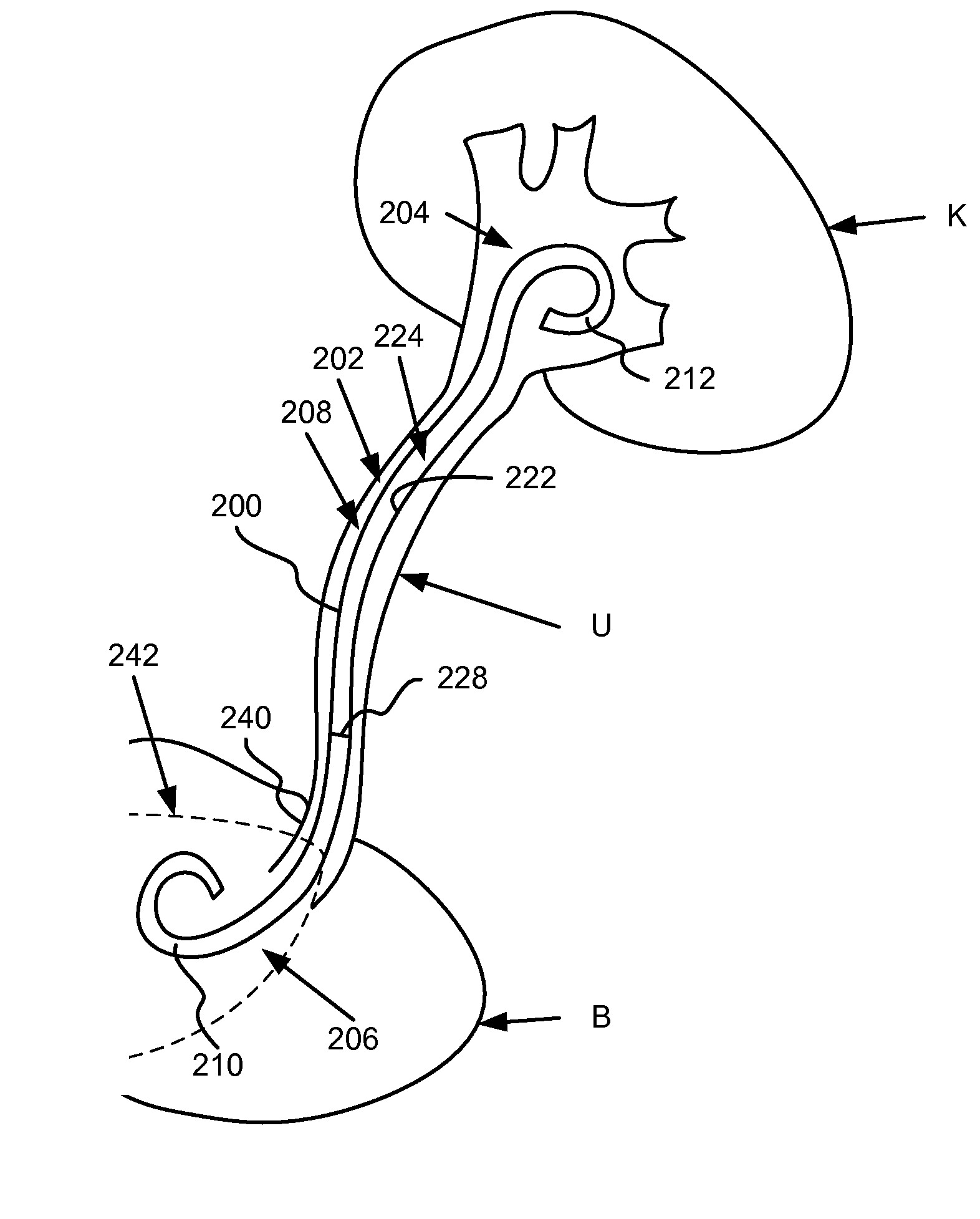
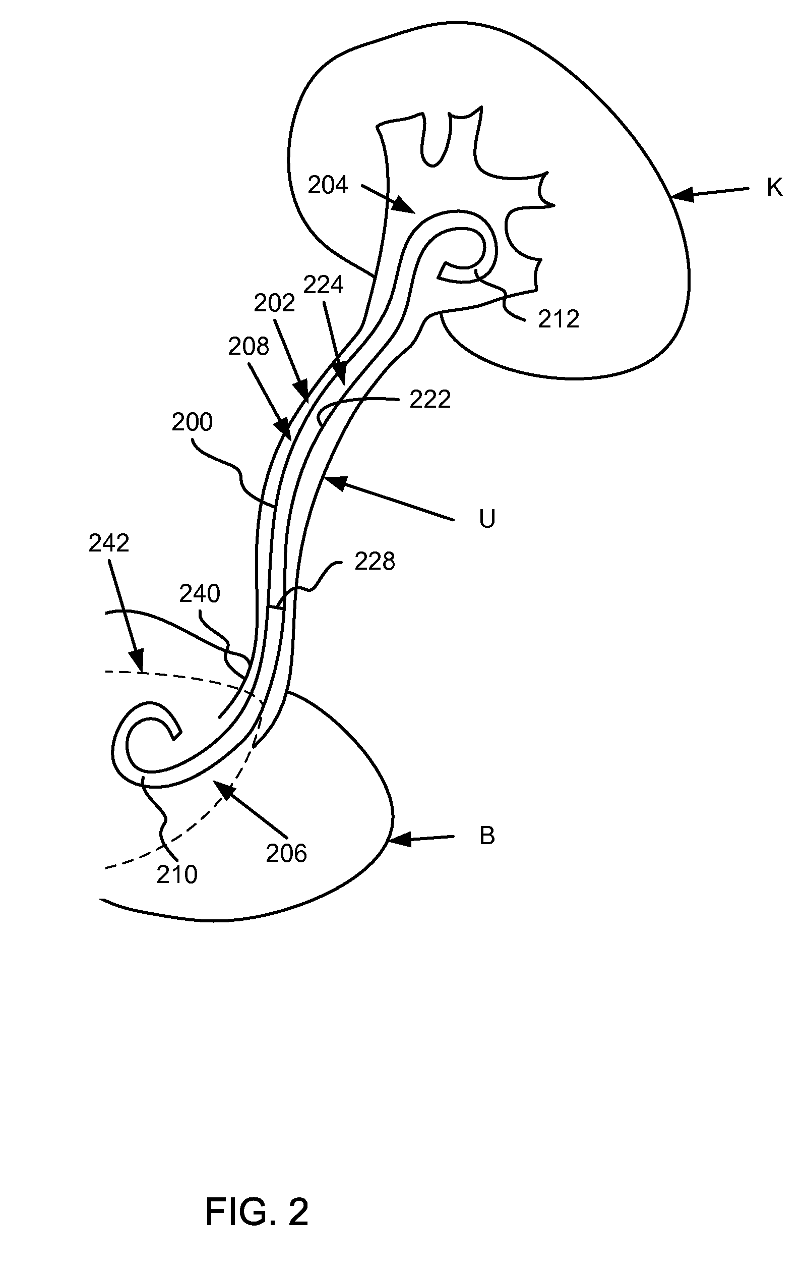
[0019]Ureteral stents having at least a portion of the ureteral stent constructed of a material that dissolves (e.g., soluble) after being exposed to a bodily fluid for a period of time are disclosed herein. Specifically, in one embodiment, the proximal end portion is configured to dissolve to substantially reduce and / or minimize irritation of sensitive regions in a bladder of a patient after the ureteral stent has been inserted. A distal end of the ureteral stent, in contrast, is constructed of a material that is formulated to be substantially stable in the bodily fluid of the patient. In some embodiments, at least a portion of a medial portion of the ureteral stent is also constructed with one or more dissolving materials. In other embodiments, the proximal portion and / or the medial portion of the ureteral stent are constructed using various combinations of dissolving and / or non-dissolving materials.

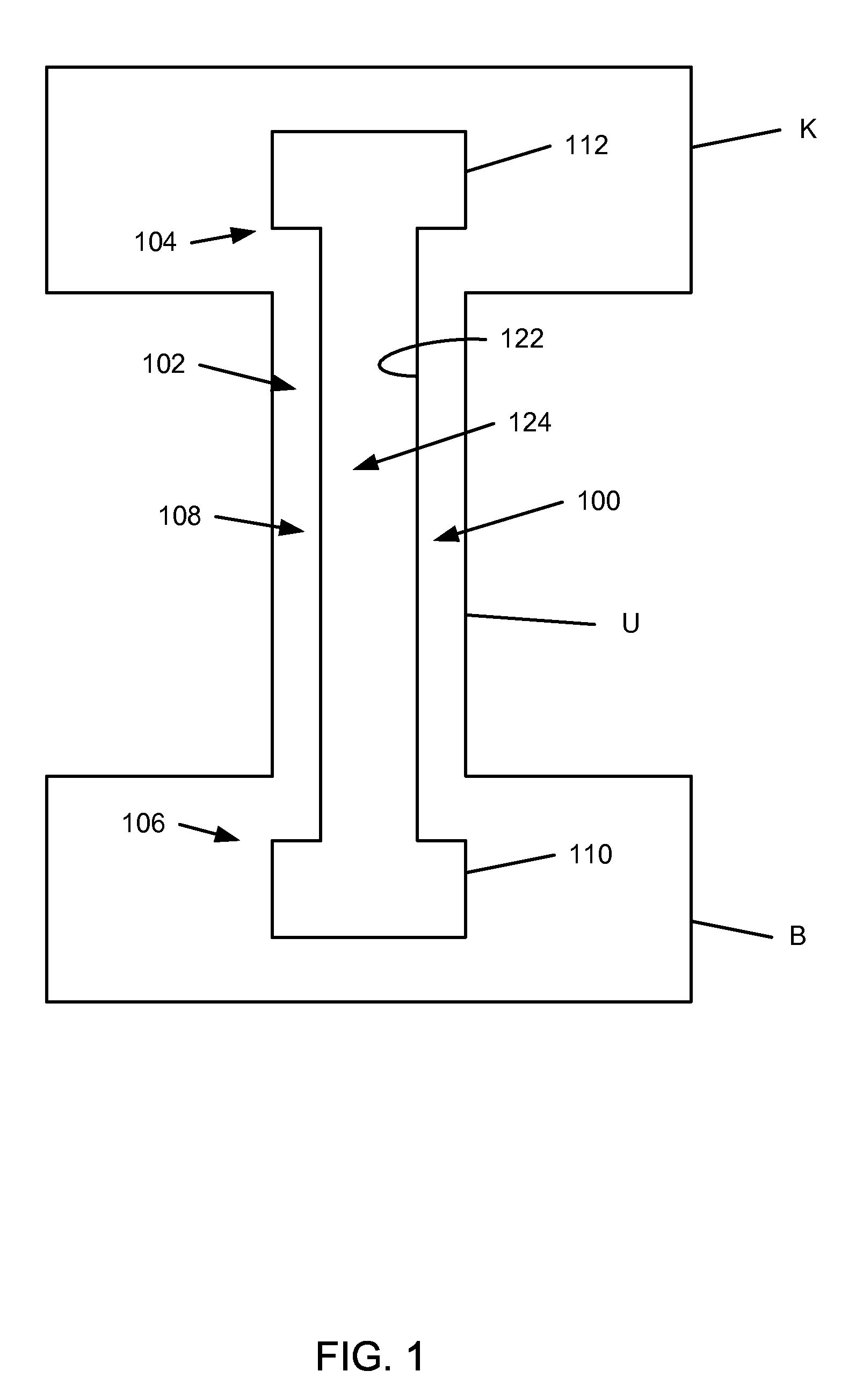
[0020]FIG. 1 is a schematic diagram that illustrates a ureteral stent 100, accordi...


PUM


Abstract

Ureteral stents having at least a portion of a proximal end of the ureteral stent constructed with a material that dissolves after being exposed to a bodily fluid for a period of time are disclosed herein. At least a portion of the proximal end portion of the elongate member includes a dissolving portion configured to dissolve in response to being exposed to a bodily fluid for a period of time. The elongate member also includes a non-dissolving portion that includes the entire retention member of the distal end portion and is substantially stable in the bodily fluid of the urinary tract of the patient. In some embodiments, a medial portion of the ureteral stent is also constructed with one or more dissolving materials. In some implementations, the proximal and / or the medial portions of the ureteral stent are constructed using various combinations of dissolving and non-dissolving materials.

Description

CROSS-REFERENCE TO RELATED APPLICATION[0001]This application claims priority to U.S. Provisional Application Ser. No. 60 / 826,642, entitled, “Stent with Soluble Bladder Retention Member,” filed on Sep. 22, 2006, which is incorporated herein by reference in its entirety.BACKGROUND[0002]The disclosed invention relates generally to a medical device, and in particular, to a ureteral stent with a dissolving portion.[0003]Known ureteral stents are typically placed within a urinary tract of a patient such that one end portion of the ureteral stent is located in a kidney of the patient and another end portion of the ureteral stent is located in either a bladder or a ureter of the patient. Known ureteral stents are typically positioned within the urinary tract of the patient by placing a guidewire within the patient, sliding the ureteral stent on the guidewire, and then forcing the ureteral stent along the guidewire into a desired position within the patient using a push rod. Such ureteral st...

Claims


Application Information

Patent Timeline
IPC IPC(8): A61F2/04
CPCA61M27/008A61M27/002A61F2/82A61F2002/048
Inventor AMOS, RAYMOND G.
Owner BOSTON SCI SCIMED INC
Why Eureka
Try Eureka