
Cornice/Skirting Mounting System

a mounting system and cornice technology, applied in the direction of walls, electrical equipment, building components, etc., can solve the problems of increasing assembly time and cost, and wasting tim

Inactive Publication Date: 2008-04-24
JACKSON ANDREW
View PDF7 Cites 32 Cited by
  • Summary
  • Abstract
  • Description
  • Claims
  • Application Information

AI Technical Summary

Benefits of technology

[0027] an elongate outer fascia removably attachable to said anchor member at one or more predetermined heights above the floor, said outer fascia including longitudinal edges adapted to abut with and bias against the wall when the outer fascia is attached to the anchor member.

Problems solved by technology

Plaster and timber cornices are difficult to erect because of their weight and the fact that they must be held in position, or tacked to the walls at their ends, while the adhesive or concrete cures.
A further difficulty with plaster and timber cornices is their inability to flex, so where the ceiling or wall may not be exactly straight, gaps appear therebetween and these must be filled, increasing assembly time and cost.
Where adjoining walls meet in a corner, it is necessary to accurately cut the corner of the cornice to obtain a neat and tidy finish at the corner, another time consuming task.
Skilled tradesmen are generally capable of achieving a neat and tidy finish, however, if the building settles with age or if there is any movement in the building, because of an earthquake for example, there is a risk that the corner join of the cornice will become separated, leading to unsightly cracks and gaps in the cornice.
These cracks and gaps can be difficult and time consuming to fill.
Moreover, the gaps can frequently open up again, even after filling, if settling of the building continues.
Timber cornices are less common nowadays because of the increasing scarcity of the recourse and higher costs involved, as well as similar mounting difficulties to those mentioned above.
However, current plastic cornice systems known to the applicant still have problems.
Firstly, the entire cornice must be held in place until the adhesive cures, and although plastic is lighter, this can still be quite difficult and time consuming.
However, existing cornice systems which include a means of detaching the outer fascia generally do not provide for a uniform and secure mounting means.
This can lead to problems such as gaps extending along the length of the cornice, instability, and in some cases, paint being scraped off the wall and / or ceiling during the process of attaching and detaching the outer fascia.
Whilst detachable skirtings exist, they are generally designed and configured for the purpose of housing wiring and not for the purpose of simplified assembly, or as a means of painting / finishing / replacing the skirting prior to, or post installation.
The attachment mechanisms are generally quite complex, and those that are known to the present inventor do not allow for a skirting outer fascia to be mounted at different heights.
For example, some skirtings are taller than others, and existing mounts or anchors may not be capable of adequately supporting such structures.

Method used


Image

  • Cornice/Skirting Mounting System
  • Cornice/Skirting Mounting System
  • Cornice/Skirting Mounting System

Examples


Embodiment Construction

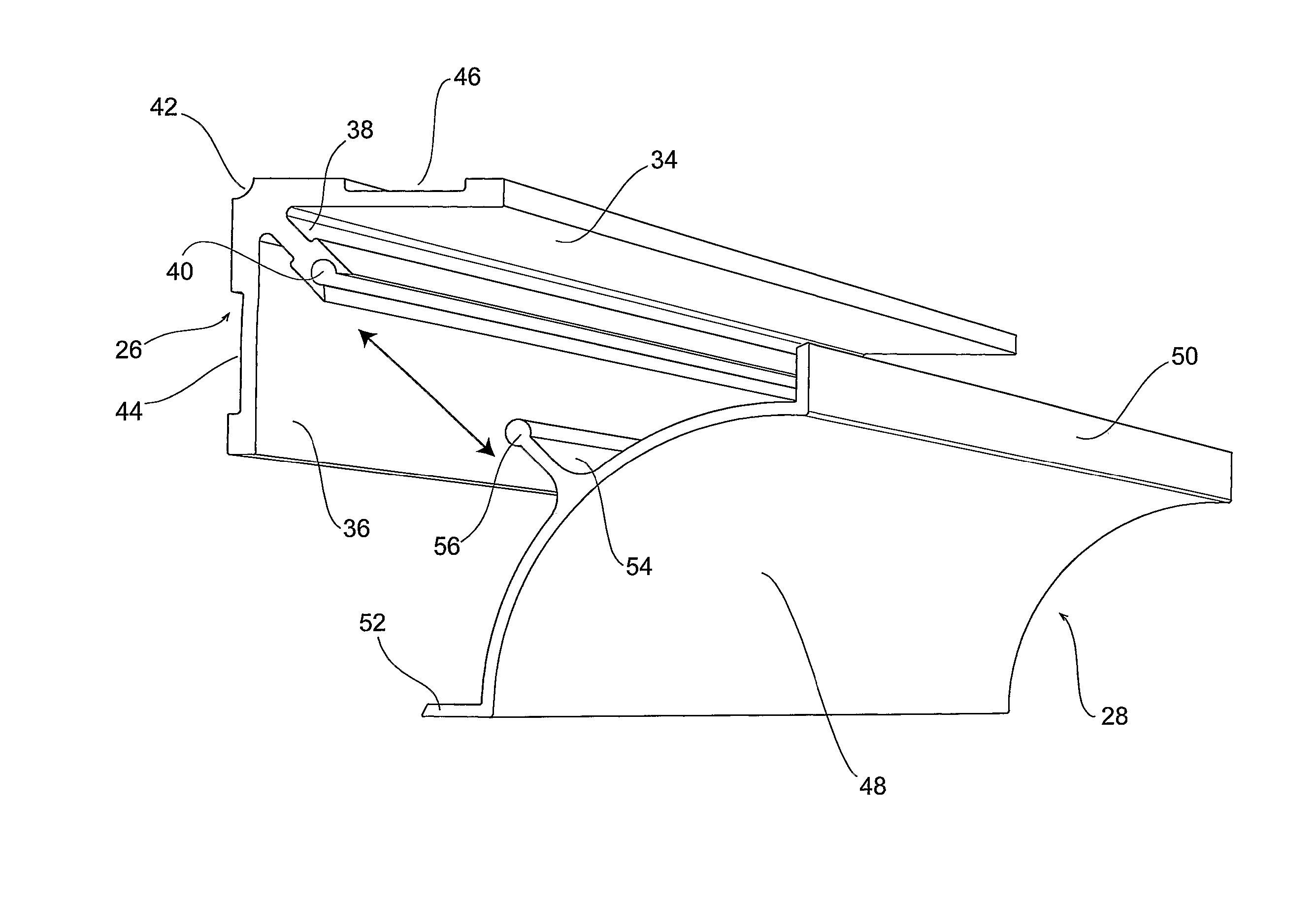
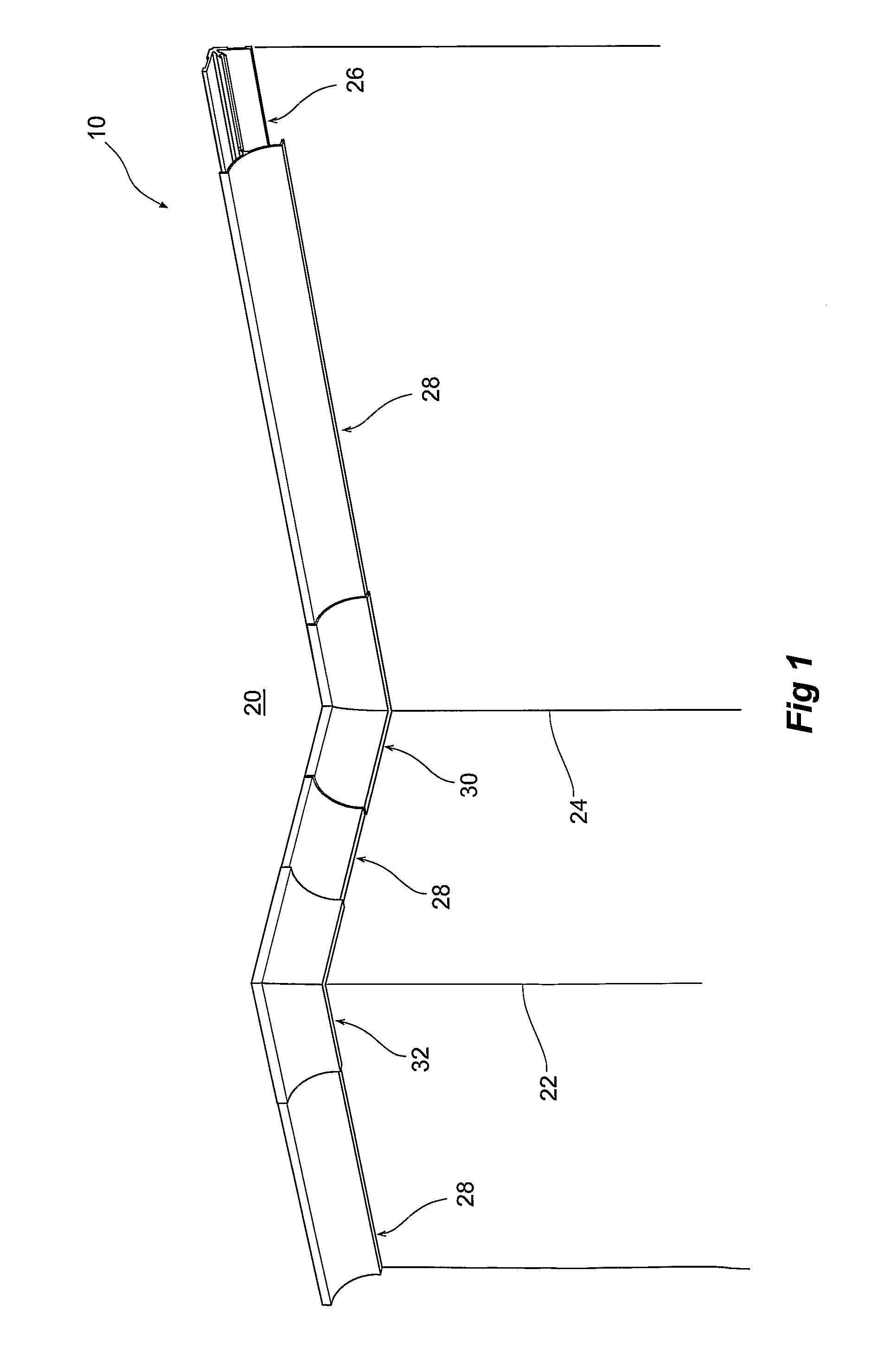
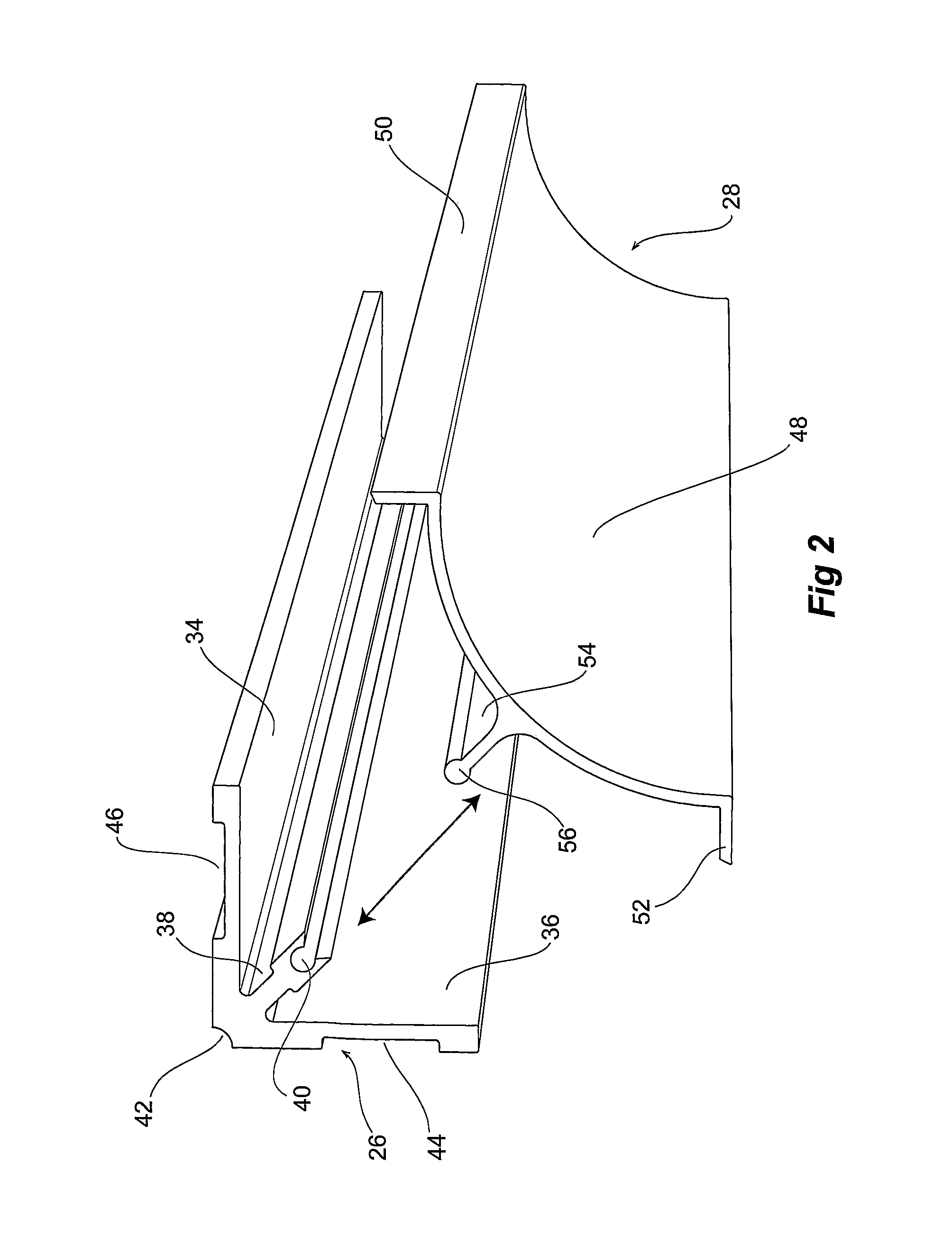
[0065] The following detailed description of the invention refers to the accompanying drawings. Although the description includes exemplary embodiments, other embodiments are possible, and changes may be made to the embodiments described without departing from the spirit and scope of the invention. Wherever possible, the same reference numbers will be used throughout the drawings and the following description to refer to the same and like parts.

[0066] The present invention relates to an improved cornice / skirting mounting system. FIG. 1 illustrates the cornice system 10 of the present invention when applied to internal walls 12 of a room, whilst FIGS. 2-8 illustrate individual components of the cornice system in more detail. Similarly, FIG. 9 illustrates the skirting system 14 of the present invention, whilst FIGS. 10-23 illustrate individual components of that system in more detail. Also forming part of the system is a wall-wall corner riser assembly 16.

[0067]FIG. 1 illustrates th...


PUM


Abstract

The present invention relates to a cornice / skirting mounting system and, in particular, to a 2-part system involving an anchor member (26) and an outer fascia member (28) which is removably attachable to the anchor member (26). The cornice / skirting mounting system of the present invention thus provides a complete system for fitting out a home with wall-wall, wall-ceiling, and wall-floor lining, with benefits prior to installation, and post-installation.

Description

[0001] The present invention relates to a cornice / skirting mounting system and, in particular, to a two-part system involving an anchor member and an outer fascia member which is removably attachable to the anchor member. BACKGROUND OF THE INVENTION [0002] The interior rooms of homes and buildings are frequently fitted out by lining the ceiling frame and wall frame with plasterboard. Typically, the floors are lined with carpet, floorboard or tiles. In order to obtain an aesthetically pleasing appearance at the junction of the walls and ceiling, and walls and floors, cornices and skirtings are often used. Similarly, architraves are used to line the perimeter of doors and windows, and the like. [0003] A cornice typically comprises a curved, elongate member that has one side in abutment with the side wall and the other side in abutment with the ceiling, or in the case of wall-wall cornices, otherwise known as risers, one side is in abutment with one wall and the other side in abutment ...

Claims


Application Information

Patent Timeline
Patent Type & Authority Applications(United States)
IPC IPC(8): E04B1/00
CPCE04F19/0436E04F19/0463H02G3/0425E04F19/0495H02G3/0418E04F19/049
Inventor JACKSON, ANDREW
Owner JACKSON ANDREW
Learn More