Luer activated device with minimal fluid displacement

a technology of activated devices and valves, applied in the direction of couplings, mechanical devices, surgery, etc., can solve the problems of reducing the potential of entrapment of particulates or contaminants, reflux is known to reduce the efficiency of catheters,

Inactive Publication Date: 2008-04-24
BAXTER INT INC +1
View PDF24 Cites 68 Cited by
  • Summary
  • Abstract
  • Description
  • Claims
  • Application Information

AI Technical Summary

Problems solved by technology

For example, the geometry of the LAD should be such that it is easily swabbable and reduces the potential of entrapping particulates or contaminan

Method used


Image

  • Luer activated device with minimal fluid displacement
  • Luer activated device with minimal fluid displacement
  • Luer activated device with minimal fluid displacement

Examples


Embodiment Construction

[0048]The embodiments disclosed herein are for the purpose of providing the required description of the present invention. These embodiment, however, are exemplary of the invention, which may be embodied in various forms. Therefore, specific details disclosed herein are not to be interpreted as limiting the invention as defined in the accompanying claims.

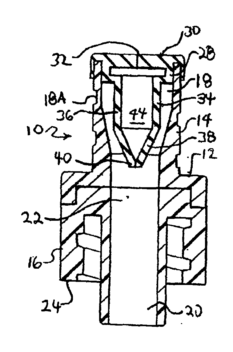
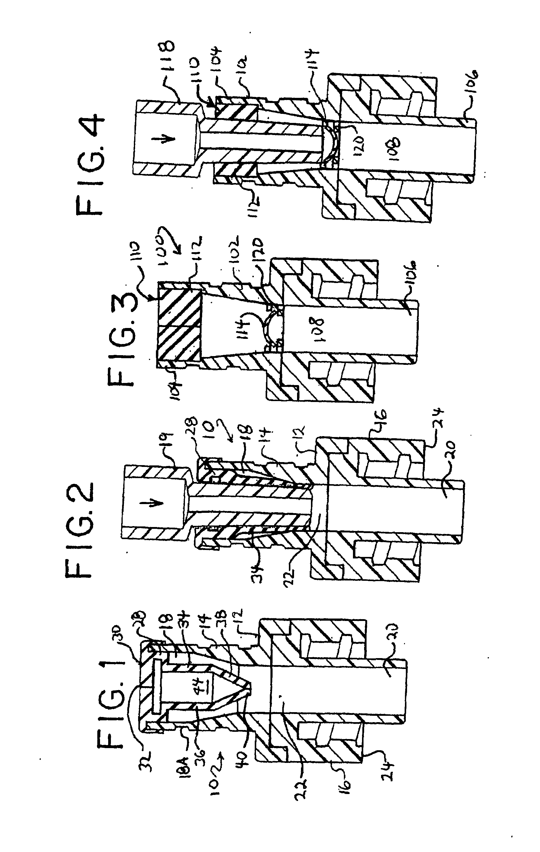
[0049]FIGS. 1 and 2 generally illustrates a first embodiment of a luer activated device (LAD) or valve of the present invention, generally designated as 10. The LAD 10 includes a valve housing 12 preferably comprised of a rigid material, such as rigid plastic or other suitable material. The LAD 10 may be provided as a unitary structure (not illustrated) or as a combination of a joined upper housing portion 14 and a lower housing portion 16. The LAD 10 also includes an inlet 18, an outlet 20, and a flow path 22 defined therebetween. The terms “inlet” and “outlet” are not to be interpreted as limiting the LAD 10 to applications involv...


PUM


Abstract

A luer activated device includes an inlet adapted to receive a male luer, an outlet associable with a fluid flow system, and a flow path defined therebetween. The inlet receives a resealable valve element having an aperture adapted to receive the male luer. The valve element is adapted such that a male luer inserted into the aperture will open fluid flow through the inlet without causing a substantial change in fluid displacement.

Description

PRIORITY CLAIM[0001]This application claims the benefit of U.S. Provisional Patent Application No. 60 / 862,502, filed Oct. 23, 2006, entitled “LUER ACTIVATED DEVICE WITH MINIMAL FLUID DISPLACEMENT”, the entire contents of which are hereby incorporated by reference and relied upon.FIELD OF THE INVENTION[0002]The present invention relates generally to luer activated devices or valves that allow for the bi-directional transfer of fluids to and from medical fluid flow systems.BACKGROUND OF THE INVENTION[0003]Luer activated devices (LAD) or valves (LAV) are commonly used in association with medical fluid containers and medical fluid flow systems that are connected to patients or other subjects undergoing diagnostic, therapeutic or other medical procedures. A LAD can be attached to or part of a fluid container or a medical fluid flow system to simplify the addition of fluids to or withdrawal of fluids from the fluid flow system.[0004]Within the medical field there are a wide variety of med...

Claims


Application Information

Patent Timeline
IPC IPC(8): F16K25/00
CPCA61M39/045A61M2039/262A61M39/26Y10S604/905
Inventor DESECKI, VINCENT C.
Owner BAXTER INT INC
Why Eureka
Try Eureka