
Wire crimping tool

a crimping tool and wire technology, applied in the field of crimping tools, can solve the problems of restricting the ability of accessing and crimping connectors, inconvenient use only one function of conventional crimping tools, so as to achieve convenient and versatile use

Inactive Publication Date: 2008-05-01
CLARK ROSS PHILLIP +1
View PDF11 Cites 2 Cited by
  • Summary
  • Abstract
  • Description
  • Claims
  • Application Information

AI Technical Summary

Benefits of technology

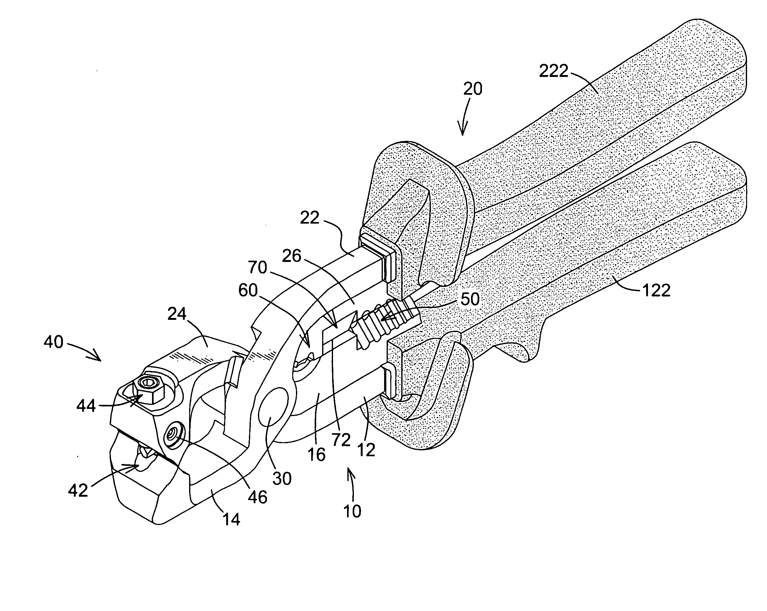
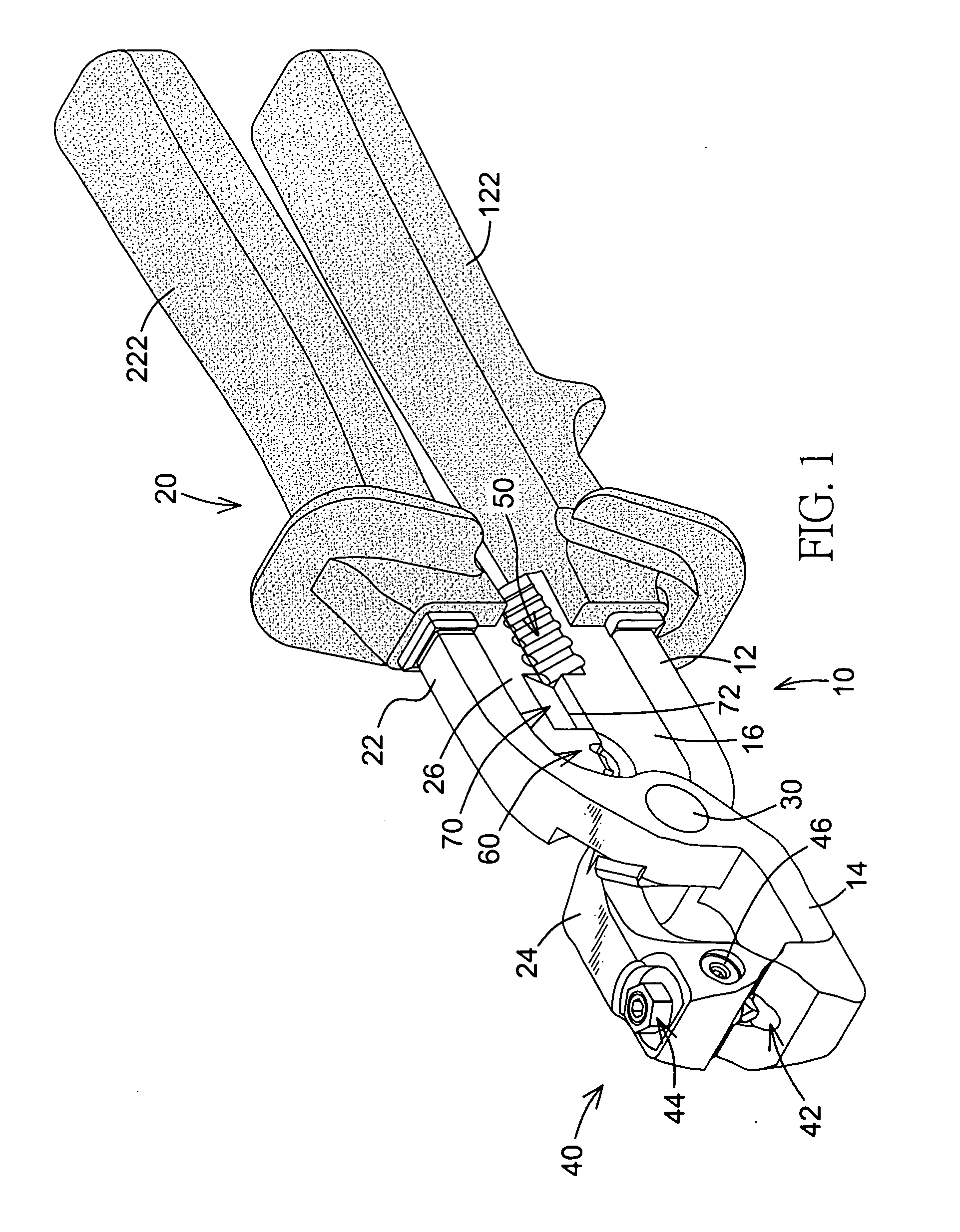
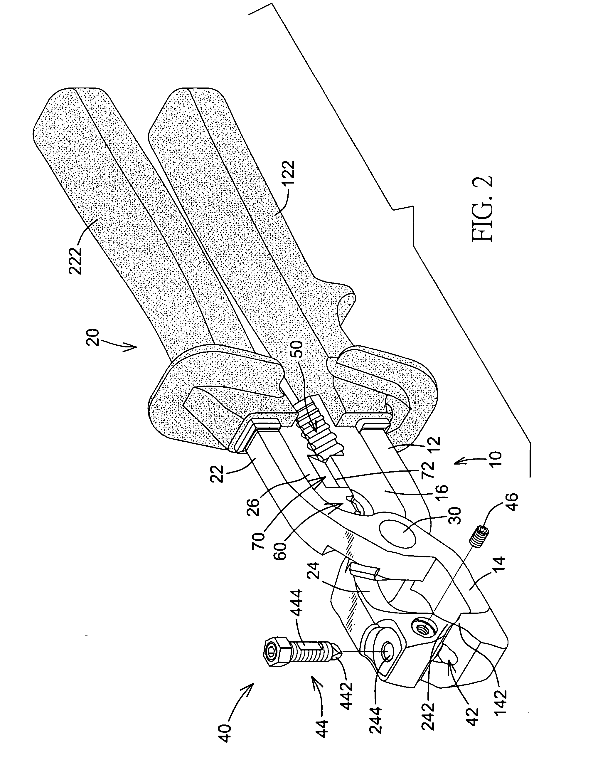
[0010]The main objective of the invention is to provide a wire crimping tool that is convenient and versatile in use. The wire crimping tool has two arms and an adjustable wire crimping device. The arms are pivotally connected to each other and each arm has two ends, a handle formed one end of the arm and a jaw formed on the other end of the arm. The adjustable wire crimping device is mounted on the jaws of the arms and has a crimping cavity and an extension member. The crimping cavity is defined in a first one of the jaws and aligns with a second one of the jaws. The crimping cavity has an upper segment with a bottom and a lower segment. The lower segment is defined in the bottom of the upper segment and has a diameter smaller than that of the upper segment. The extension member is adjustably mounted in the second jaw and has a crimping tip extending out of the second jaw and aligning with and extending into the crimping cavity.

Problems solved by technology

However, the conventional crimping tool must be used perpendicular to the lengths of the crimped wire, so the angle of operation of the conventional crimping tool restricts the ability of accessing and crimping connectors to wires which are located in confined or narrow spaces.
Therefore, the conventional crimping tool is inconvenient in use.
Conventional crimping tools can achieve only one function and is not versatile in use.
However, although extension member and the hole of the wire crimping means of the conventional wire crimping tool are threaded to make the length of the crimping tip protruding from the hole is adjustable, the crimping groove corresponding to the extension member has only one size and cannot be fit with different connectors with different diameters.
Therefore, this conventional wire crimping tool is also not versatile in use.

Method used


Image

  • Wire crimping tool
  • Wire crimping tool
  • Wire crimping tool

Examples


Embodiment Construction

[0021]With reference to FIGS. 1 and 2, a wire crimping tool in accordance with the present invention comprises two arms (10,20) and an adjustable wire crimping device (40). The arms (10,20) are pivotally connected to each other with a pivot (30). Each arm (10,20) having two ends, a handle (12,22) formed one end of the arm (10,20) and a jaw (14,24) formed on the other end of the arm (10,20). Each arm (10,20) has a coat (122,222) made of an insulating material mounted around the handle (12,22) of the arm (10,20).

[0022]Each jaw (14,24) is C-shaped to define a space between the jaws (14,24). With further reference to FIGS. 3 and 4, the jaws (14,24) each have a cutting end (142,242) facing and selectively abutting against with each other, and the cutting end (142,242) of each jaw (14,24) has a triangular section to form a sharp tip (143,243) on the cutting end (142,242). The sharp tips (143,243) can be used to cut a wire and strip the insulation off wires.

[0023]With further reference to ...


PUM

PropertyMeasurementUnit
diameteraaaaaaaaaa
diametersaaaaaaaaaa
insulatingaaaaaaaaaa

Abstract

A wire crimping tool has two arms and an adjustable wire crimping device. The arms are pivotally connected to each other and each arm has a handle and a jaw. The adjustable wire crimping device is mounted on the jaws of the arms and has a duel crimping cavity and a threaded extension member. The duel crimping cavity is defined in a first one of the jaws and aligns with a second one of the jaws. The duel crimping cavity has an upper segment with a bottom and a lower segment. The lower segment is defined in the bottom of the upper segment and has a diameter smaller than that of the upper segment. The threaded extension member is adjustably mounted in the second jaw and has a crimping tip extending out of the second jaw and aligning with and extending into the duel crimping cavity.

Description

BACKGROUND OF THE INVENTION[0001]1. Field of the Invention[0002]The present invention relates to a crimping tool, and more particularly to a wire crimping tool that is adjustable for crimping different connectors with different diameters and is versatile in use.[0003]2. Description of Related Art[0004]To connect a wire with a connector, such as a male or female pin or a crimp eyelet or to connect two wires via a connecting sleeve, a crimping tool is always used. A conventional wire crimping tool substantially comprises a pair of pliers and a crimping device. The crimping device may comprise multiple teeth formed on the mouth of the plier head.[0005]However, the conventional crimping tool must be used perpendicular to the lengths of the crimped wire, so the angle of operation of the conventional crimping tool restricts the ability of accessing and crimping connectors to wires which are located in confined or narrow spaces. Therefore, the conventional crimping tool is inconvenient in ...

Claims


Application Information

Patent Timeline
Patent Type & Authority Applications(United States)
IPC IPC(8): B21F15/00
CPCH01R43/0421
Inventor CLARK, ROSS PHILLIPCLARK, HEATHER LORRAINE
Owner CLARK ROSS PHILLIP
Learn More