
Sweep with guide surface

a technology of guide surface and sweep, which is applied in the field of sweep with guide surface, can solve the problems of user inability to control the angle between the profile and the other geometry, and is extremely difficult to construct using the rail,

Inactive Publication Date: 2008-05-01
AUTODESK INC
View PDF19 Cites 8 Cited by
  • Summary
  • Abstract
  • Description
  • Claims
  • Application Information

AI Technical Summary

Benefits of technology

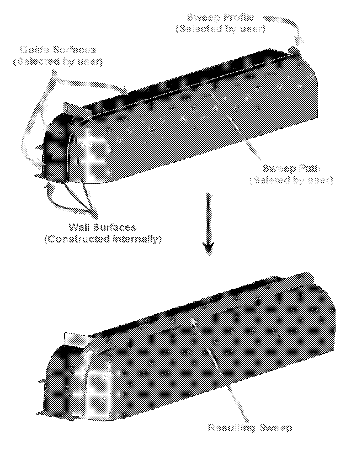
[0017]One or more embodiments of the invention provide the ability to create a Normal to Surface Sweep; a sweep feature that will allow the selection of a guide surface (in addition to a profile and a path), the normal of which will control the twist of the swept profile about the path.

Problems solved by technology

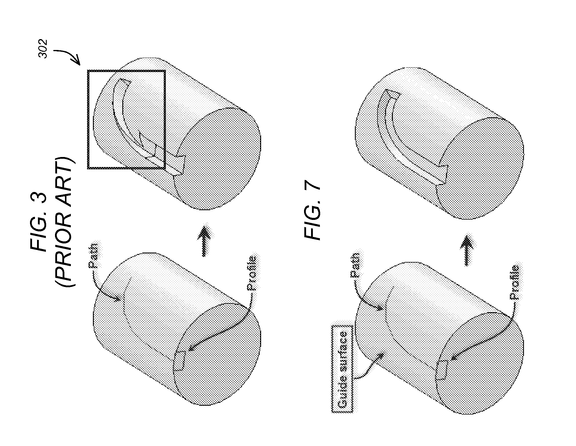
However, a sweep along a curved surface (e.g., across multiple surfaces and / or complex surfaces) can be extremely difficult to construct using rails and can often provide unexpected results.
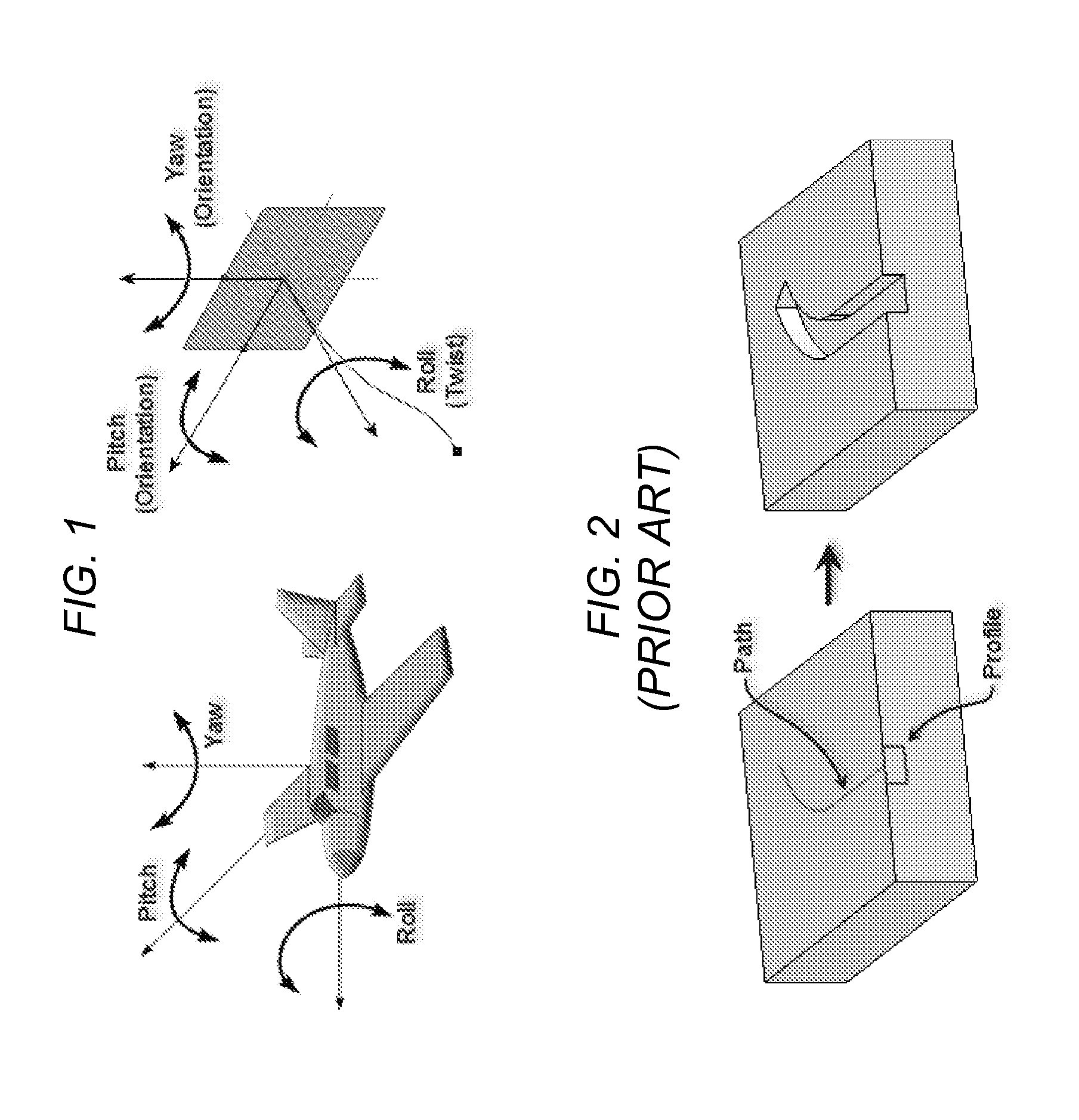
However, when the path crosses over multiple surfaces, the sweep operation may provide an unpredictable result because the profile is twisted or rolled in an undesirable manner.
However, the user is not able to control the angle between the profile and the other geometry as the sweep is performed along the path.
As illustrated, the ambiguity in the profile twist control can cause unexpected results 302.
In this regard, as the profile is swept across the non-planar surfaces the profile twist causes the profile to change its orientation in an undesirable manner.
However, in the prior art use of two rails, it is difficult and complex to construct the second curve.

Method used


Image

  • Sweep with guide surface
  • Sweep with guide surface
  • Sweep with guide surface

Examples


Embodiment Construction

[0033]In the following description, reference is made to the accompanying drawings which form a part hereof, and which is shown, by way of illustration, an embodiment of the present invention. It is understood that other embodiments may be utilized and structural changes may be made without departing from the scope of the present invention.

[0034]Hardware and Software Environment

[0035]FIG. 4 is an exemplary hardware and software environment used to implement one or more embodiments of the invention. Embodiments of the invention are typically implemented using a computer 400, which generally includes, inter alia, a display device 402, data storage devices 404, cursor control devices 406, and other devices. Those skilled in the art will recognize that any combination of the above components, or any number of different components, peripherals, and other devices, may be used with the computer 400.

[0036]One or more embodiments of the invention are implemented by a computer-implemented gra...


PUM


Abstract

A method, apparatus, and article of manufacture provide the ability to conduct a sweep operation in a computer-implemented solid modeling system, A 3D non-planar surface is created. A path for a sweep operation is created. A profile for the sweep operation is created. The 3D surface is selected for use as a guide. An angle between the profile and the 3D non-planar surface is calculated. A sweep operation is conducted wherein a twist of the profile is maintained within a pre-defined range of the angle.

Description

CROSS-REFERENCE TO RELATED APPLICATIONS[0001]This application is related to the following co-pending and commonly-assigned patent applications, which applications are incorporated by reference:[0002]U.S. Pat. No. 6,906,711, filed on Jun. 21, 2001, and issued on Jun. 14, 2005 by Kenneth J. Hill, entitled “GRAPH-BASED METHOD FOR MULTI-BODIED SWEEP TERMINATIONS, which application claims priority to provisional patent application Ser. No. 60 / 269,831, filed on Feb. 20, 2001, by Kenneth J. Hill, entitled “GRAPH-BASED METHOD FOR MULTI-BODIED SWEEP TERMINATIONS,” and attorney's docket number 30566.126USP1.BACKGROUND OF THE INVENTION[0003]1. Field of the Invention[0004]The present invention relates to computer-aided design (CAD) systems, and in particular, to controlling the twist / roll of a sweep operation in a computer-implemented solid modeling system.[0005]2. Description of the Related Art[0006]Over the last few decades, designers have changed their fundamental approach to graphics design...

Claims


Application Information

Patent Timeline
Patent Type & Authority Applications(United States)
IPC IPC(8): G06T17/00
CPCG06T17/10
Inventor ZHAO, KANGLEBOVITZ, PAUL R.
Owner AUTODESK INC
Learn More