Plasma display device and driving method thereof

a technology of a display device and a driving method, applied in the direction of static indicating devices, instruments, etc., can solve problems such as dynamic false contours, and achieve the effect of reducing the difference between subgroups in light intensity

Inactive Publication Date: 2008-05-08
SAMSUNG SDI CO LTD
View PDF2 Cites 0 Cited by
  • Summary
  • Abstract
  • Description
  • Claims
  • Application Information

AI Technical Summary

Benefits of technology

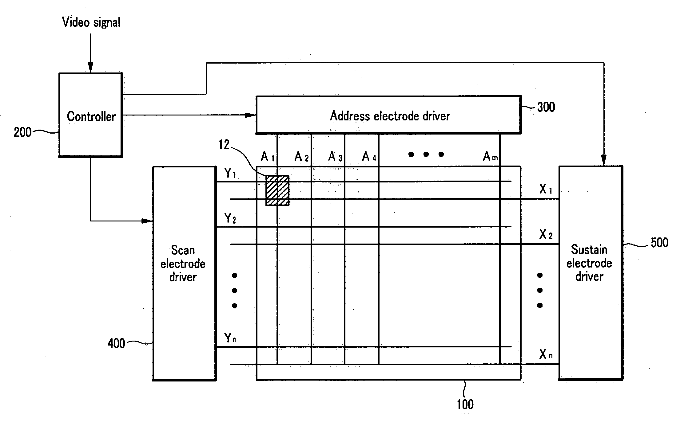
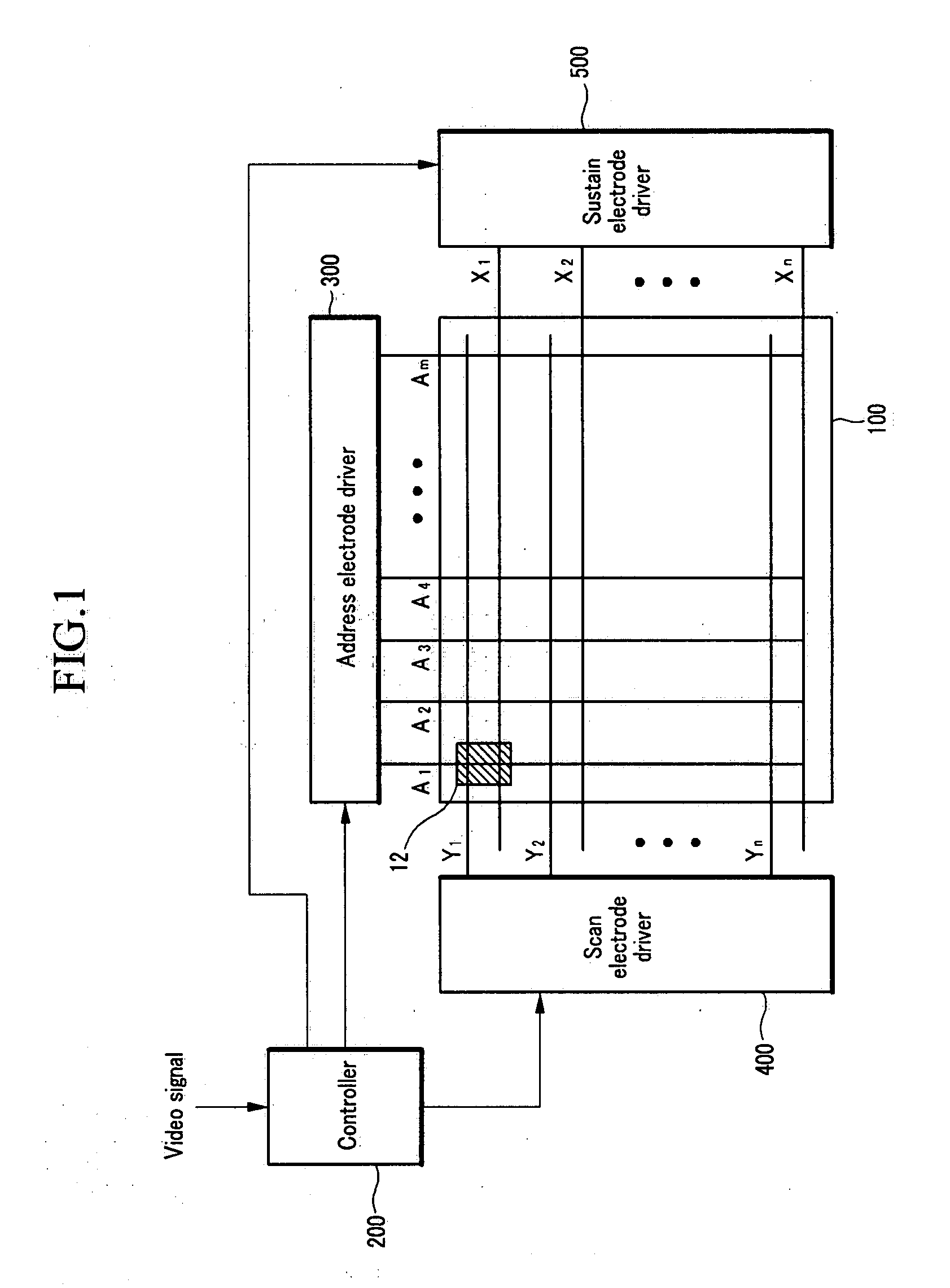
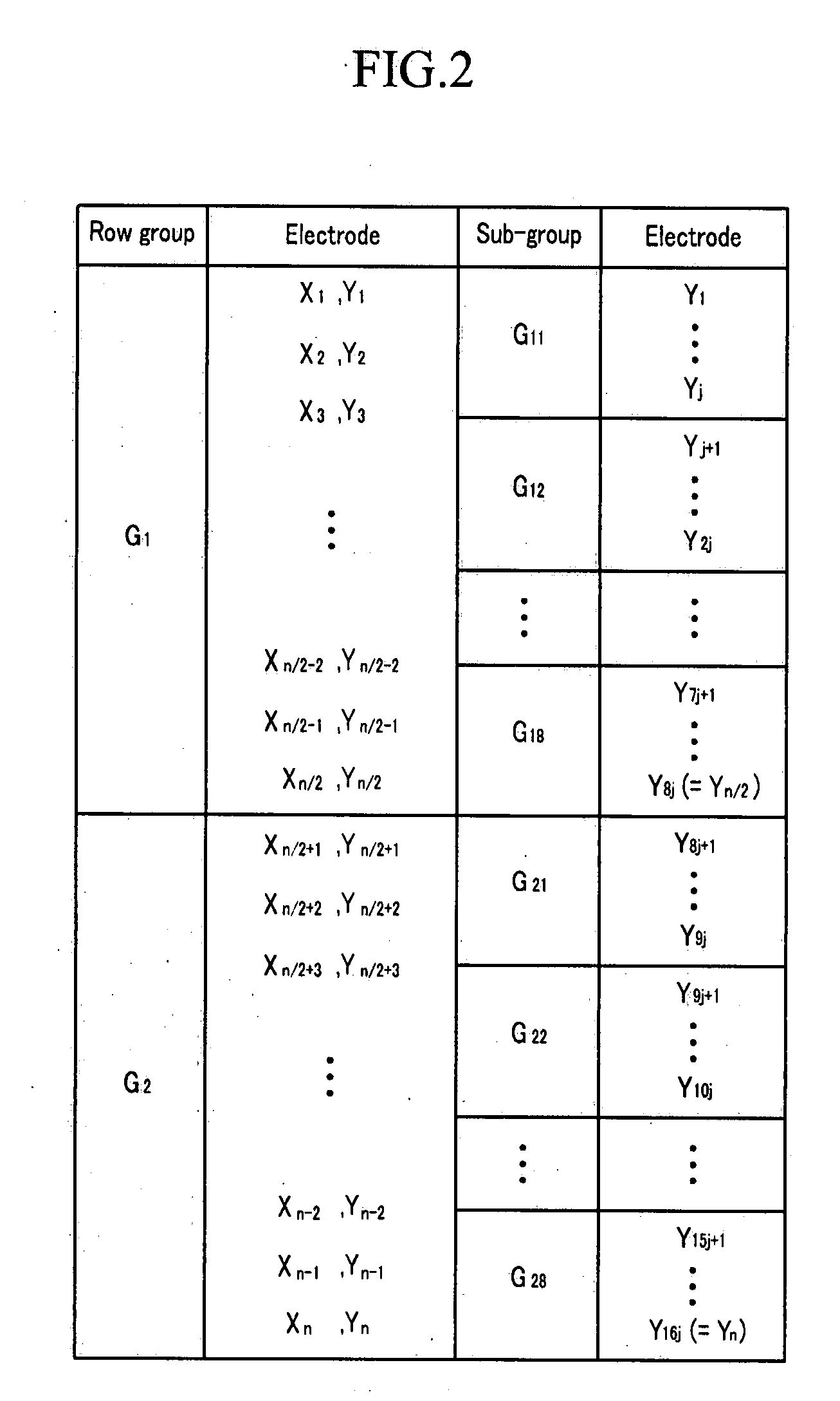
[0012] It is therefore another feature of an embodiment of the present invention to provide a plasma display device, and a method of driving the same, in which a luminance difference between subgroups may be reduced by changing a subgroup to which at least one row electrode is assigned.

Problems solved by technology

The operation described above of expressing grayscales using subfields may cause a dynamic false contour.

Method used


Image

  • Plasma display device and driving method thereof
  • Plasma display device and driving method thereof
  • Plasma display device and driving method thereof

Examples


Embodiment Construction

[0026] Korean Patent Application No. 10-2006-0109455, filed on Nov. 7, 2006, in the Korean Intellectual Property Office, and entitled: “Plasma Display and Driving Method Thereof,” is incorporated by reference herein in its entirety.

[0027] The present invention will now be described more fully hereinafter with reference to the accompanying drawings, in which exemplary embodiments of the invention are illustrated. The invention may, however, be embodied in different forms and should not be construed as limited to the embodiments set forth herein. Rather, these embodiments are provided so that this disclosure will be thorough and complete, and will fully convey the scope of the invention to those skilled in the art. Like reference numerals refer to like elements throughout.

[0028] As used herein, “wall charges” refer to charges formed and accumulated on a wall (e.g., a dielectric layer) close to an electrode of a discharge cell. A wall charge may be described as being “formed” or “acc...


PUM


Abstract

A method for driving a plasma display device having a plurality of row electrodes and a plurality of discharge cells corresponding to the row electrodes, in which a field is divided into a plurality of subfields, the method including dividing the plurality of row electrodes into at least a first row group and a second row group, dividing the first row group into a plurality of first subgroups, dividing the second row group into a plurality of second subgroups, and address-discharging one of the first subgroups while sustain-discharging a corresponding one of the second subgroups during a predetermined subfield of a first field, wherein at least one row electrode is part of one subgroup in a first field, and the at least one row electrode is part of another subgroup in a second field.

Description

CROSS-REFERENCE TO RELATED APPLICATION [0001] This application is related to co-pending U.S. patent application Ser. No. ______, entitled “PLASMA DISPLAY DEVICE AND DRIVING METHOD THEREOF,” which was filed on Oct. 19, 2007, and which is incorporated by reference herein in its entirety.BACKGROUND OF THE INVENTION [0002] 1. Field of the Invention [0003] Embodiments relate to a plasma display device and a method of driving the same. [0004] 2. Description of the Related Art [0005] A plasma display device is a flat panel display device that uses plasma generated by a gas discharge to display images, e.g., text, video, etc. It may include a plasma display panel (PDP) having, depending on its size, tens to millions of discharge cells, which may be arranged in a matrix format. [0006] In operation of the plasma display device, a field (e.g., one TV field) may be divided into respectively weighted subfields. Grayscales may be expressed by a combination of weights from among the subfields. A d...

Claims


Application Information

Patent Timeline
Patent Type & Authority Applications(United States)
IPC IPC(8): G09G3/28
CPCG09G3/2022G09G2310/0218G09G3/2935G09G3/2932G09G3/291G09G3/296
Inventor CHAE, SEUNG-HUN
Owner SAMSUNG SDI CO LTD
Why Eureka
Try Eureka