Linear roller bearing

a technology of roller bearings and rollers, applied in the direction of sliding contact bearings, linear bearings, bearings, etc., can solve the problems of shortened service life, increased local pressure, and inability to adjust the raceway elements

Inactive Publication Date: 2008-05-08
AMK ARNOLD MUELLER
View PDF8 Cites 14 Cited by
  • Summary
  • Abstract
  • Description
  • Claims
  • Application Information

AI Technical Summary

Benefits of technology

[0009]As a result, the individual raceway elements may self-adjust in all directions and independently of each other, so that—if the profiles extending through the linear roller bearing deflect, and if connecting pieces enclosing it become deformed—the load is distributed among the individual rolling elements in an extraordinarily even manner, due to the automatic self-adjustment of the individual raceway elements. The raceway elements are tiltable around their l

Problems solved by technology

The raceway elements are not adjustable.
They react to deformations under stress with excess loads, which result in increased local pressure and, therefore, to a shortened service life.
Self-adjusting linear roller bearings of this type have the disadvantage that they are adjustable only to a minimal extent in the longitudinal direction, e.g., by 0.5°.
The adjustment capability is limited by the tarnishing of the raceway plates, which are curved only slightly, in the receiving bore of the connecting piece.
The connecting pieces are still deformed plastically when high loads are applied and impacts occur.
In summary, known linear roller bearings have the disadvantage of reduce

Method used


Image

  • Linear roller bearing
  • Linear roller bearing
  • Linear roller bearing

Examples


Embodiment Construction

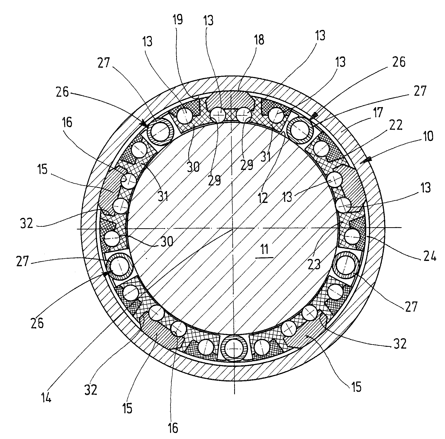
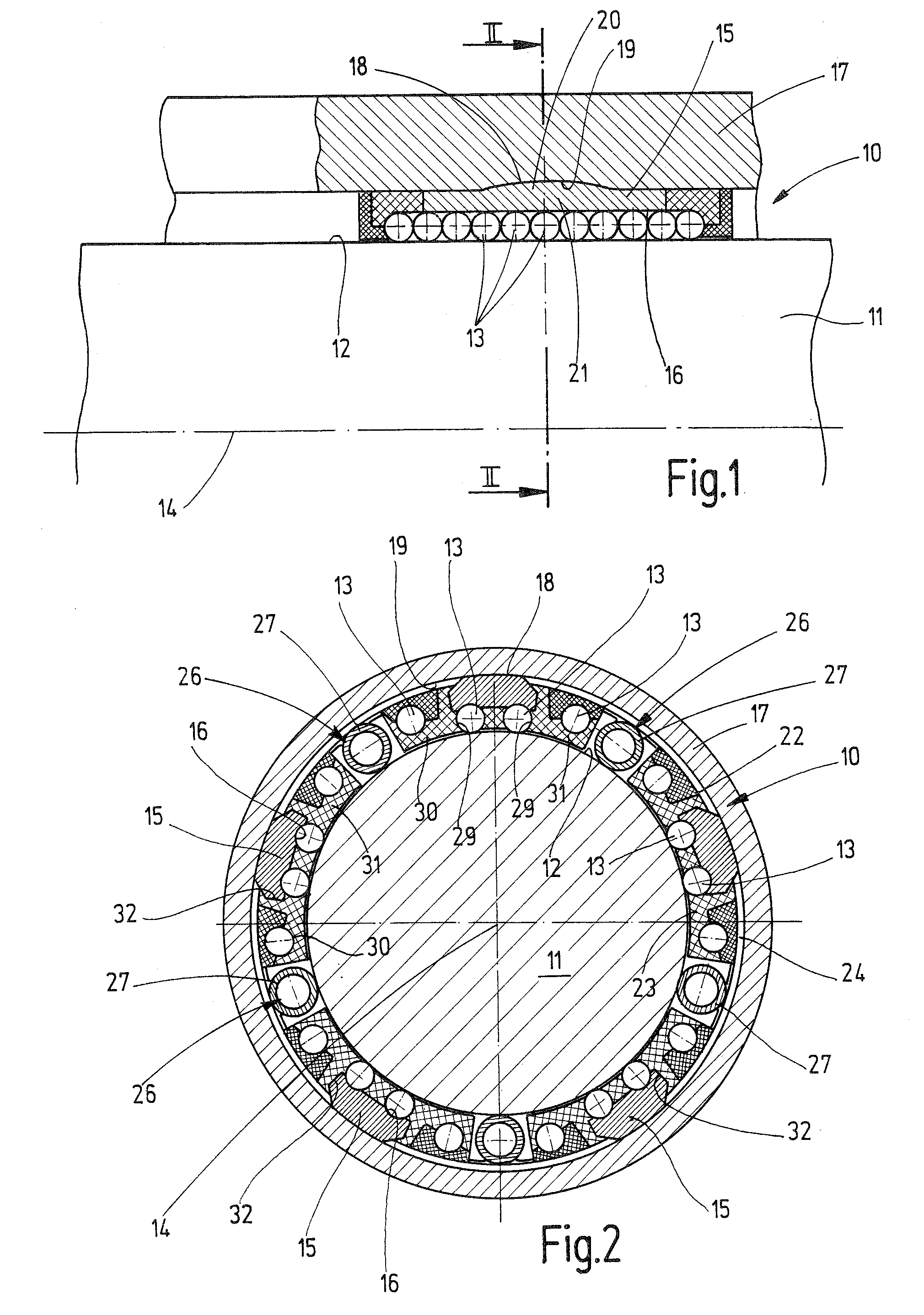
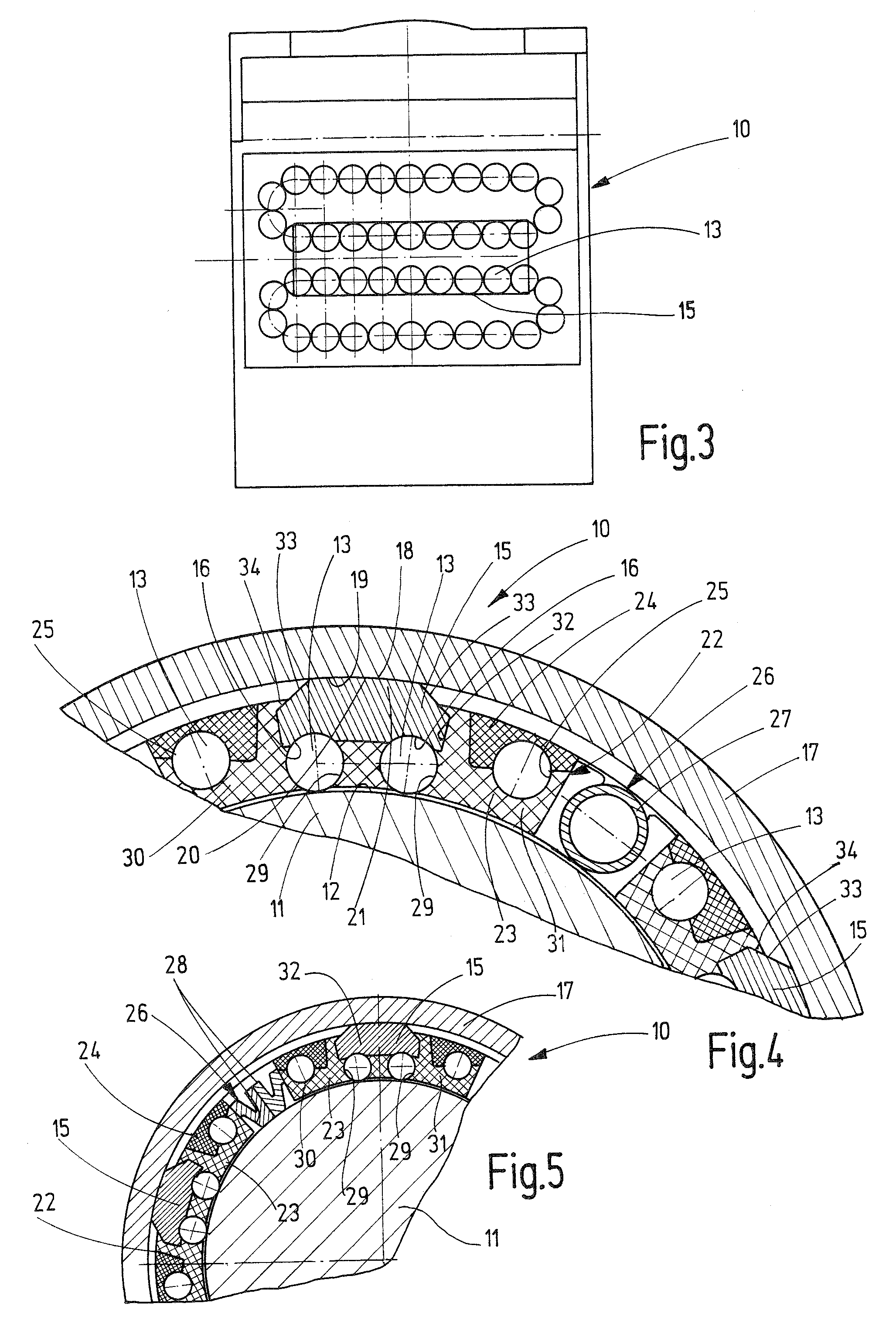
[0026]FIGS. 1 through 4 are schematic depictions of a linear roller bearing 10 according to a first exemplary embodiment, which is located on a profile 11 in the form of a shaft in this case. This profile has a circular cross section in this case, although it may have a different cross section. On its outer surface 12, profile 11 includes raceways for rolling elements 13 of linear roller bearing 10. Rolling elements 13 may have diverse designs. Advantageously, they are composed, e.g., of balls or cylindrical rollers or barrel-shaped rollers, or the like. Rolling elements 13 are located in individual rows of rolling elements, which extend essentially parallel to the longitudinally-extending central axis 14 of bearing 10 and to each other, and are distributed around a circle, as viewed in the cross section in FIG. 2. Raceway elements 15 are assigned to these rows of rolling elements—provided they are load-bearing rolling elements 13—each of which includes carrier raceway 16 of at leas...


PUM


Abstract

A linear roller bearing has raceway elements, which are grouped around the central axis of the bearing, include rows of rolling elements distributed around a circle—as viewed in the cross section—and which are essentially parallel to each other and to the central axis of the bearing, the raceway elements being by enclosed in the circumferential direction by at least one connecting piece on at least one longitudinal section such that the raceway elements bear via the outer surface of the longitudinal section against a facing inner surface of the at least one connecting piece. The inner surface and the outer surface are curved biaxially and bear against each other in two dimensions, thereby resulting in a design similar to that of a ball joint.

Description

CROSS-REFERENCE TO A RELATED APPLICATION[0001]The invention described and claimed hereinbelow is also described in German Patent Application DE 10 2006 052 597.3 filed on Nov. 8, 2006. This German Patent Application, whose subject matter is incorporated here by reference, provides the basis for a claim of priority of invention under 35 U.S.C. 119(a)-(d).BACKGROUND OF THE INVENTION[0002]The present invention relates to a linear roller bearing.[0003]A linear roller bearing of the aforementioned type is known (EP 1199485 A1), with which the individual raceway elements are accommodated via their circular arc-shaped outer surfaces in a matching cylindrical inner bore of a connecting piece, which encloses the raceway element structure. The raceway elements are not adjustable. They react to deformations under stress with excess loads, which result in increased local pressure and, therefore, to a shortened service life.[0004]Self-adjusting linear guides (DE 19 49 182 A1) are also known. The...

Claims


Application Information

Patent Timeline
IPC IPC(8): F16C29/06
CPCF16C23/04F16C29/069F16C29/001F16C31/06
Inventor MUELLER, ARNOLD
Owner AMK ARNOLD MUELLER
Why Eureka
Try Eureka