Respiratory Therapy Device and Method

a technology of respiratory therapy and airway, applied in the direction of respirators, machines/engines, mechanical equipment, etc., can solve the problems of relatively high cost, relatively sensitive airway devices, and inability to carry active respiratory therapy systems, and achieve the effect of facilitating one or more additional therapies

Active Publication Date: 2008-05-15
SUNMED GRP HLDG LLC
View PDF59 Cites 47 Cited by
  • Summary
  • Abstract
  • Description
  • Claims
  • Application Information

AI Technical Summary

Benefits of technology

[0008]Some aspects in accordance with principles of the present disclosure relate to a device for providing respiratory therapy to a patient during at least a portion of a patient breathing cycle otherwise including an inspiratory phase and an expiratory phase. The device includes a housing and an interrupter valve assembly. The housing includes a patient inlet, an exhaust outlet, a chamber, and a pressurized fluid supply inlet. The chamber is fluidly disposed between the patient inlet and the exhaust outlet. The interrupter valve assembly is associated with the housing and includes a control port fluidly connecting the patient inlet and the chamber. Further, the interrupter valve assembly includes a valve body adapted to selectively obstruct fluid flow through the control port. With this in mind, the device is adapted to operate in a first, passive mode and a second, active mode. In the passive mode, positive airflow to the supply inlet does not occur. The interrupter valve assembly interacts with exhaled air from the patient to create an oscillator

Problems solved by technology

While relatively inexpensive and viable, the Flutter device is fairly sensitive, requiring the patient to maintain the device at a particular angle to achieve a consistent PEP effect.
However, a positive pressure source is required, such that available active respiratory therapy systems are not readily portable, and are r

Method used


Image

  • Respiratory Therapy Device and Method
  • Respiratory Therapy Device and Method
  • Respiratory Therapy Device and Method

Examples


Embodiment Construction

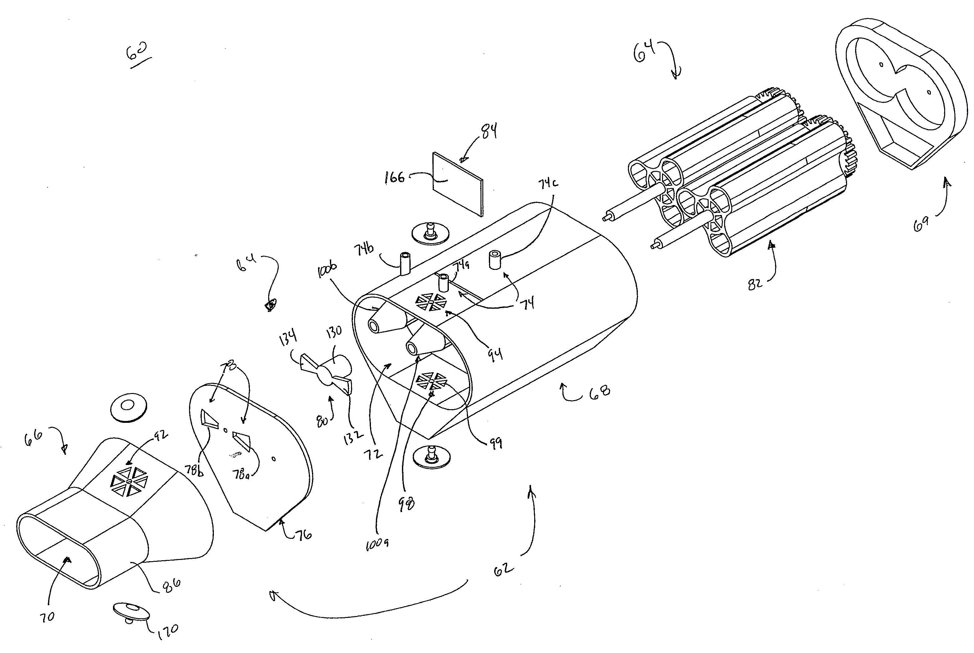
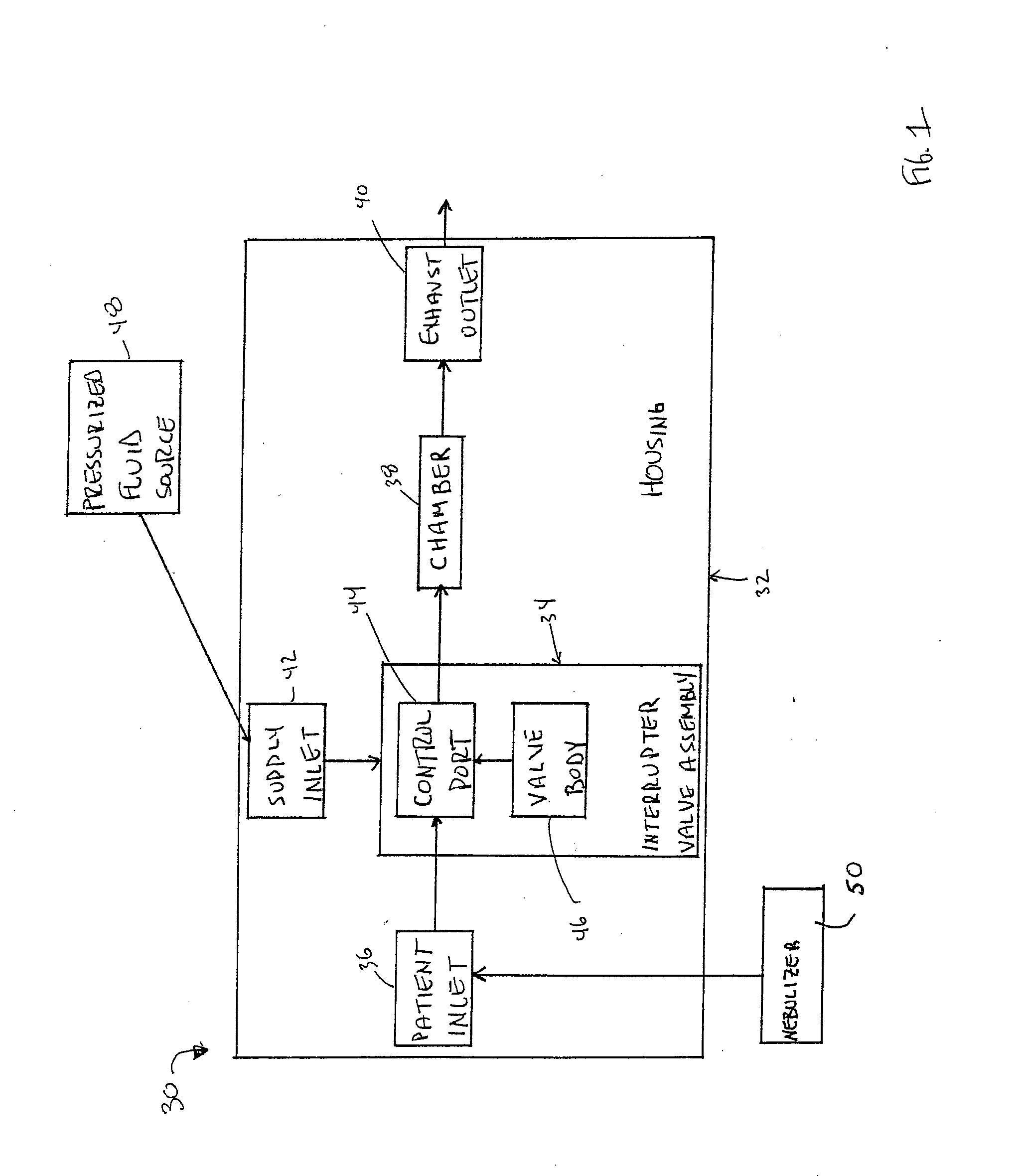
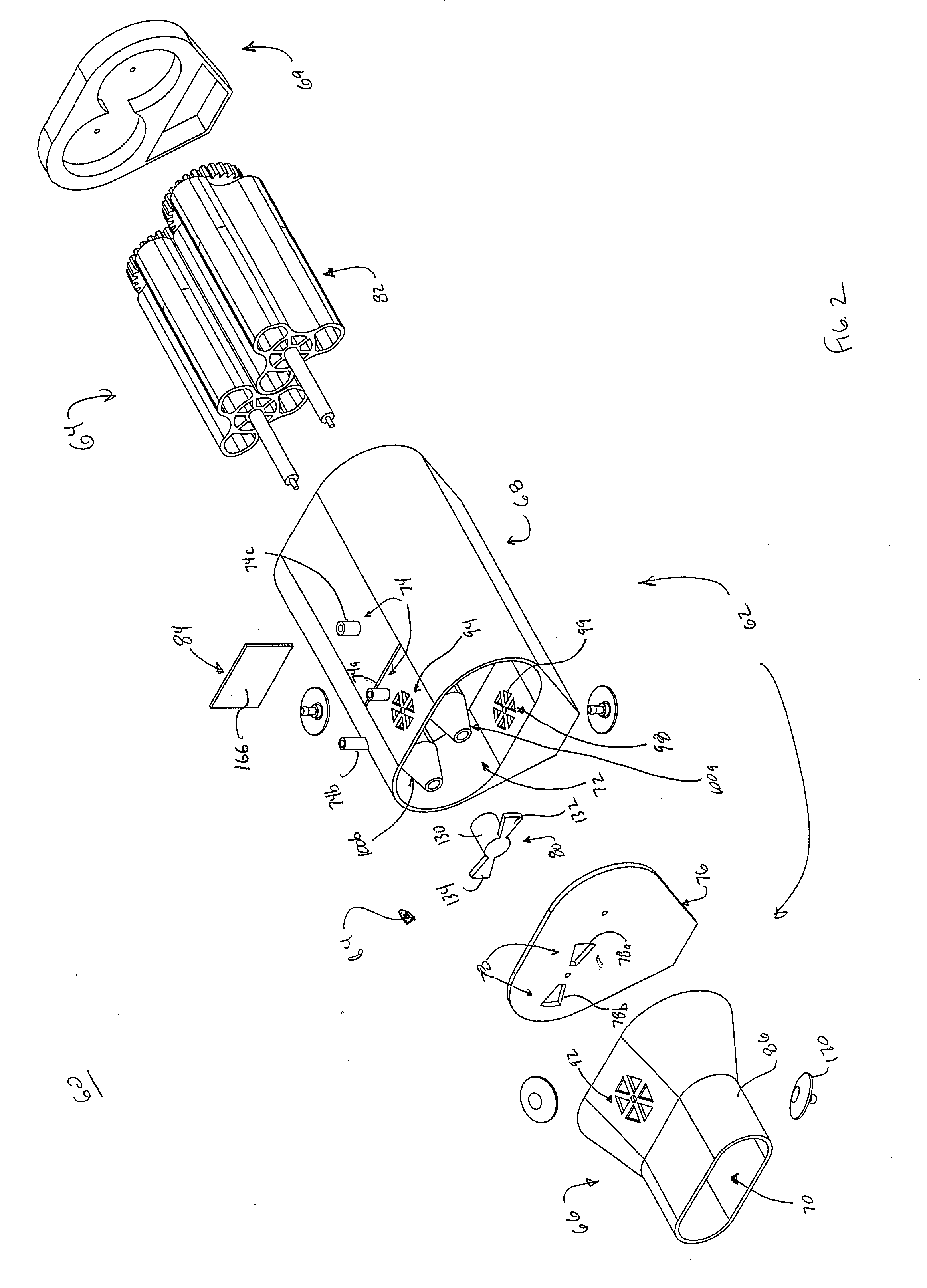
[0046]In general terms, aspects of the present disclosure relate to respiratory therapy devices and related methods of use that are: 1) capable of operating in either of an active mode (e.g., CHFO) or a passive mode (e.g., oscillatory PEP); or 2) improved passive-only oscillatory PEP devices; or 3) improved active-only devices (CHFO and / or CPAP). As used throughout this specification, an “active” therapy device is in reference to a device that requires a separate source of positive pressure fluid to effectuate a designated respiratory therapy, whereas a “passive” therapy device is in reference to a device that delivers a designated respiratory therapy in and of itself (i.e., a separate source of positive pressure fluid is not necessary). Thus, an “active-only” therapy device is one that must be connected to a separate source of positive pressure fluid. Conversely, a “passive-only” therapy device is one that is not configured to receive pressurized fluid from a separate source. Given...


PUM


Abstract

A respiratory therapy device including a housing and an interrupter valve assembly. The housing includes a patient inlet, an exhaust outlet, a chamber, and a supply inlet. The interrupter valve assembly is associated with the housing and includes a control port fluidly connecting the patient inlet and the first chamber, and a valve body adapted to selectively obstruct fluid flow through the control port. In a passive mode, positive fluid flow to the supply inlet does not occur, and the interrupter valve assembly interacts with exhaled air create an oscillatory PEP effect. In an active mode, fluid flow to the supply inlet occurs and the interrupter valve assembly operates to create a CHFO effect. The respiratory device can serve as a passive oscillatory PEP device, and when connected to a positive pressure source, as an active device.

Description

BACKGROUND OF THE INVENTION[0001]The present disclosure relates to respiratory therapy devices and methods for administering breathing-relating treatments (e.g., oscillatory, continuous, etc.) to a patient. More particularly, it relates to respiratory therapy devices capable of creating oscillatory respiratory pressure pulses in response to the patient's expiratory airflow alone, or when connected to a source of positive pressure fluid (e.g., air, oxygen, etc.), or both. One or more additional therapies (e.g., continuous positive airway pressure, continuous positive expiratory pressure, delivery of aerosolized medication, etc.) are optionally available in some embodiments.[0002]A wide variety of respiratory therapy devices are currently available for assisting, treating, or improving a patient's respiratory health. For example, positive airway pressure (PAP) has long been recognized to be an effective tool in promoting bronchial hygiene by facilitating improved oxygenation, increase...

Claims


Application Information

Patent Timeline
IPC IPC(8): A61M11/00A61M16/00A61M16/20
CPCA61M11/00A61M16/00A61M16/20A61M16/208A61M16/202F01C13/00F01C20/24A61M16/0006F01C1/123A61M16/209
Inventor DUNSMORE, THOMAS J.WISE, GEOFFREY C.WILSCHKE, THOMAS C.MATICE, CHRISTOPHER J.GILLUM, CHRISTOPH L.READ, SHANNON RICE
Owner SUNMED GRP HLDG LLC
Why Eureka
Try Eureka