Eureka AIR delivers breakthrough ideas for toughest innovation challenges, trusted by R&D personnel around the world.

Status management device and status management method

a status management and status technology, applied in the field of status management system, can solve the problems of difficult to update the presence information in real time, the watcher cannot know the difference between real presence information and the presence information, and the presentity is difficult to allow or deny

Inactive Publication Date: 2008-05-29
FUJITSU LTD
View PDF7 Cites 21 Cited by
  • Summary
  • Abstract
  • Description
  • Claims
  • Application Information

AI Technical Summary

Benefits of technology

The present invention provides a status management device that can manage presence information of presentities in a network. The device allows or denies publishers from updating presence information based on a configuration provided by a presentity. The device also notifies the presentity of changes in presence information in real-time, while keeping the presentity's privacy. The device can also correlate buddies with watchers to allow or deny updates based on the buddies' response. The device can also store processing rules for processing status information and notify the presentity of changes in presence information based on the processing rules. The technical effects of the invention include improved management of presence information and better privacy protection for presentities.

Problems solved by technology

In that case, however, it is difficult for presentity A to allow or deny all the possible publishers prior to updating presence information therefrom.
This makes it difficult to update presence information in real time and to notify it to a watcher.
As a result, the watcher cannot know the difference between real presence information and the presence information that the watcher is seeing even though presence information has been already changed.
On the other hands if presence information updated by a publisher that a presentity does not recognize is stored as the presentity's presence information, the presentity's privacy might be invaded.

Method used


Image

  • Status management device and status management method
  • Status management device and status management method
  • Status management device and status management method

Examples


first embodiment

>

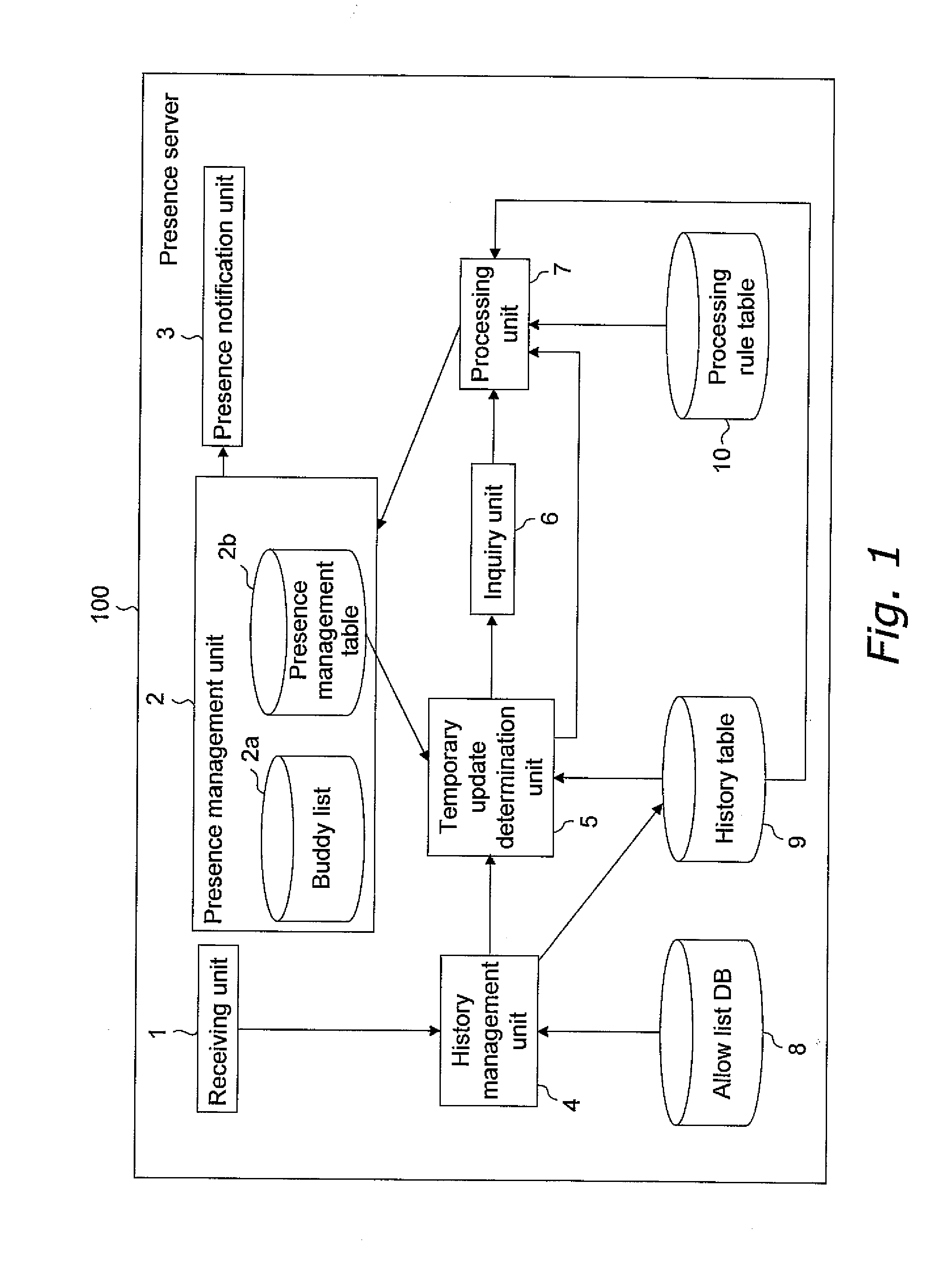
[0067]Now, a functional configuration of the presence server 100 according to a first embodiment of the present invention will be explained with reference to FIG. 1. The presence server 100 is configured with a computer terminal having a CPU, a ROM, a RAM, a hard disk, etc. The CPU of the presence server 100 functions as a receiving unit 1, a presence management unit 2, a presence notification unit 3, a history management unit 4, a temporary update determination unit 5, an inquiry unit 6 and a processing unit 7. Further, the presence server 100 has a buddy list 2a, a presence management table 2b, an allow list database (hereinafter abbreviated as DB) 8, a history table 9 and a processing rule table 10 on the ROM and the hard disk. First, an explanation for each data base and table, and then for the function of each unit is given. In the present status management system, each client can be uniquely specified by a client ID.

[0068]Database and Table

(1) Buddy List

[0069]FIG. 3 is a conc...

second embodiment

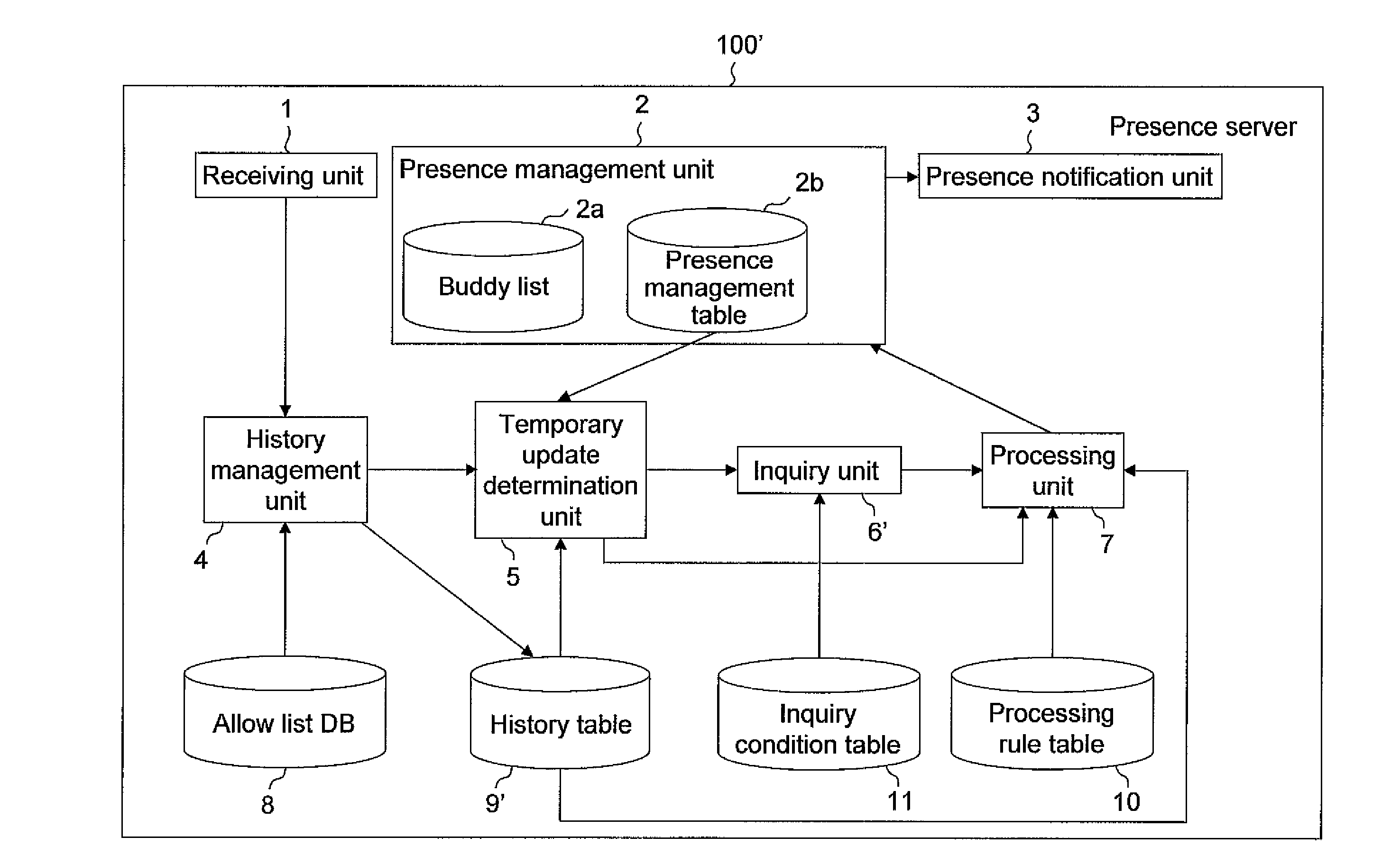
[0115]The presence server 100 in the first embodiment transmits an inquiry to a presentity every time a status update command is received from a publisher. A presence server 100′ in the present embodiment, on the other hand, an inquiry as to whether or not to allow or to deny a plurality of status update commands is collectively transmitted to the presentity.

>

[0116]FIG. 11 is a block diagram showing a functional configuration of a presence server 100′ according to a second embodiment. In the figure, the same reference numerals are assigned to the blocks that have the same function described in the first embodiment. A CPU of the presence server 100′ functions as a receiving unit 1, a presence management unit 2, a presence notification unit 3, a history management unit 4, a temporary update determination unit 5, an inquiry unit 6′ and a processing unit 7. Further, the presence server 100′ has a buddy list 2a, a presence management table 2b, an allow list database (hereinafter abbrevia...


PUM


Abstract

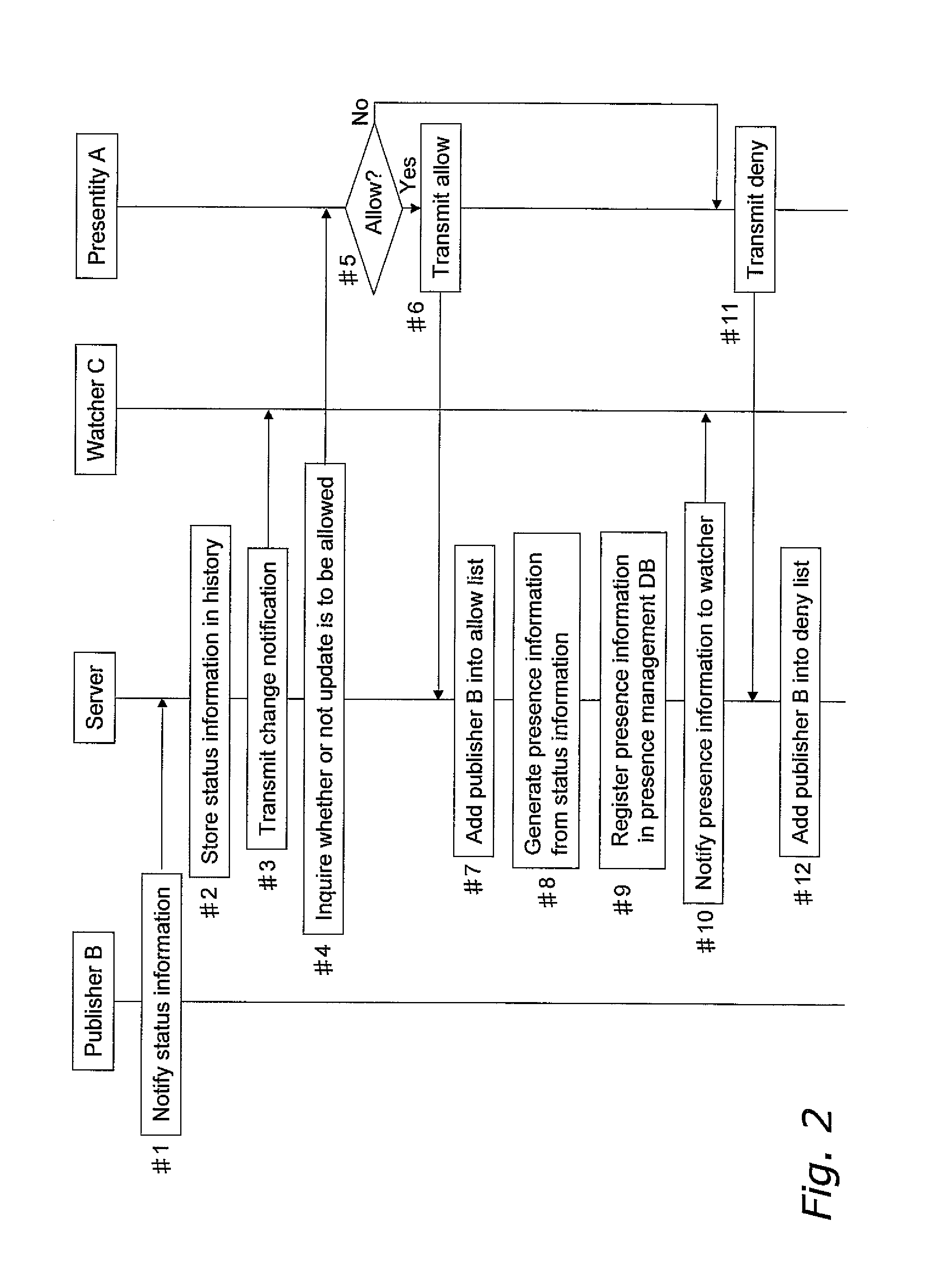
An object of the present invention is to manage presence update by publishers that a presentity does not recognize.When the presence server 100 receives status information that indicates a status of presentity A from publisher B (#1), the presence server 100 stores it in the history table 9 and transmits a change notification to a watcher C (#3). Subsequently, the presence server 100 makes an inquiry to presentity A as to whether or not to allow an update by publisher B (#4). When it is allowed (#5, #6), publisher B is added in the allow list 8a of the allow list DB 8 (#7). Also, presence information is generated based on status information retrieved from the history table 9 (#8), is notified to the watcher C and is stored in the presence management DB 2b (#9, #10). When it is denied (#11), publisher B is added in the deny list 8b of the allow list DB 8 (#12). Also, status information received from publisher B is deleted from the history table 9.

Description

BACKGROUND OF THE INVENTION[0001]1. Field of the Invention[0002]The present invention relates to a status management system that manages and notifies status information of presentity. The status management system includes a presence server and a plurality of clients. The presence server stores the status information (hereinafter referred to as presence information) receives from any given client C1, and distributes it to other clients C2.[0003]Presentity is a client that possesses presence information. Watcher is a destination client to which presence information of a presentity is distributed. Buddy is a presentity that provides its presence information for a watcher. Publisher is a client that updates presence information of a presentity other than itself. It does not matter whether or not a presentity allows the publisher to update its presence information.[0004]2. Related Art[0005]In anticipation of a coming ubiquitous society, a status management system has been proposed in whi...

Claims


Application Information

Patent Timeline
Patent Type & Authority Applications(United States)
IPC IPC(8): G06F7/00G06F17/30
CPCH04L67/24H04L67/54
Inventor KAKUTA, JUNOKUYAMA, SATOSHI
Owner FUJITSU LTD
Why Eureka
Eureka Blog
Learn More