
Developing apparatus

a technology of developing apparatus and sheet metal, applied in the field of developing apparatus, can solve problems such as sheet metal dropping

Active Publication Date: 2008-06-12
CANON KK
View PDF16 Cites 20 Cited by
  • Summary
  • Abstract
  • Description
  • Claims
  • Application Information

AI Technical Summary

Benefits of technology

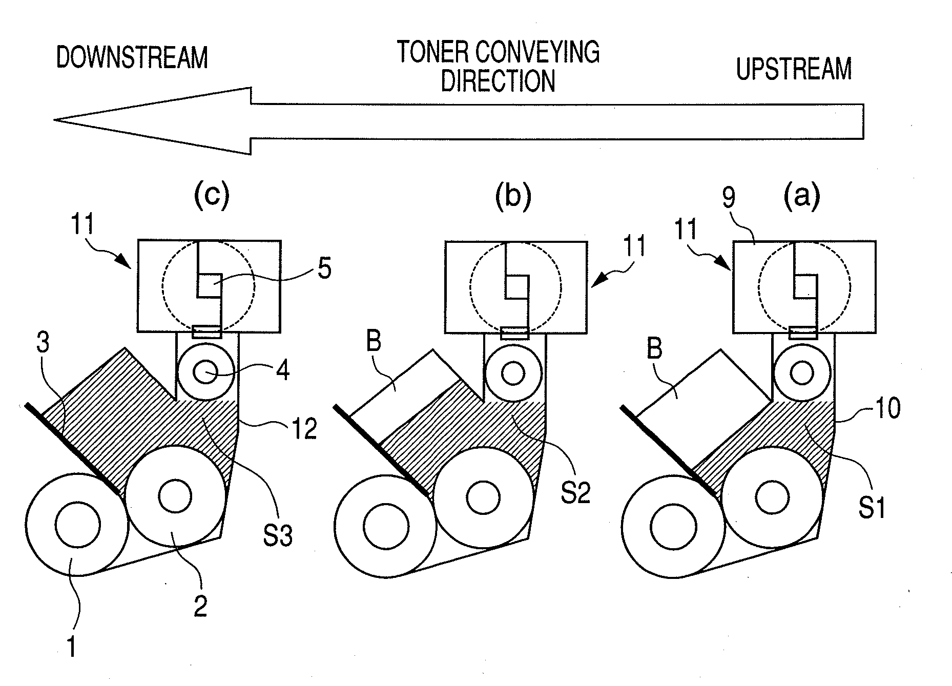
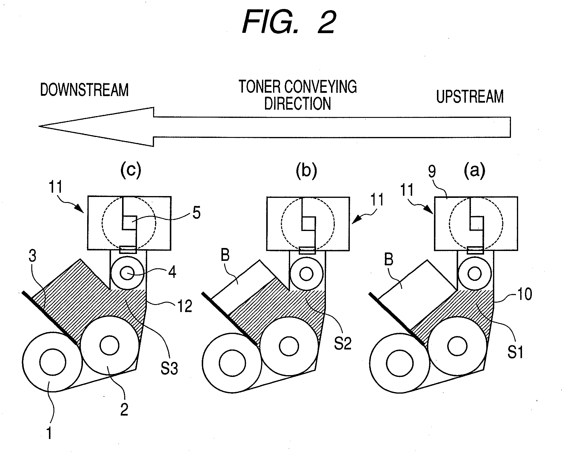
[0017]The present invention provides a developing apparatus that can secure a uniform density of a developer along a developer conveying direction of a developer conveying member corresponding to a longitudinal direction of a developer carrying member.
[0018]Also, the present invention provides a developing apparatus that can suppress the shading of density of the developer in a longitudinal direction of a developer carrying member.
[0019]Also, the present invention provides a developing apparatus that can perform adequately an agitation of the developer.

Problems solved by technology

In this case, when physical properties of both the existing toner and the replenished toner are greatly different, so-called coarseness or fog on a white background portion may occur in a half-tone image, and there occur defects such as a dropping on sheet.
Incidentally, there are common problems to be solved in the developing apparatus disclosed in Japanese Patent Application Laid-Open No.

Method used


Image

  • Developing apparatus
  • Developing apparatus
  • Developing apparatus

Examples


Embodiment Construction

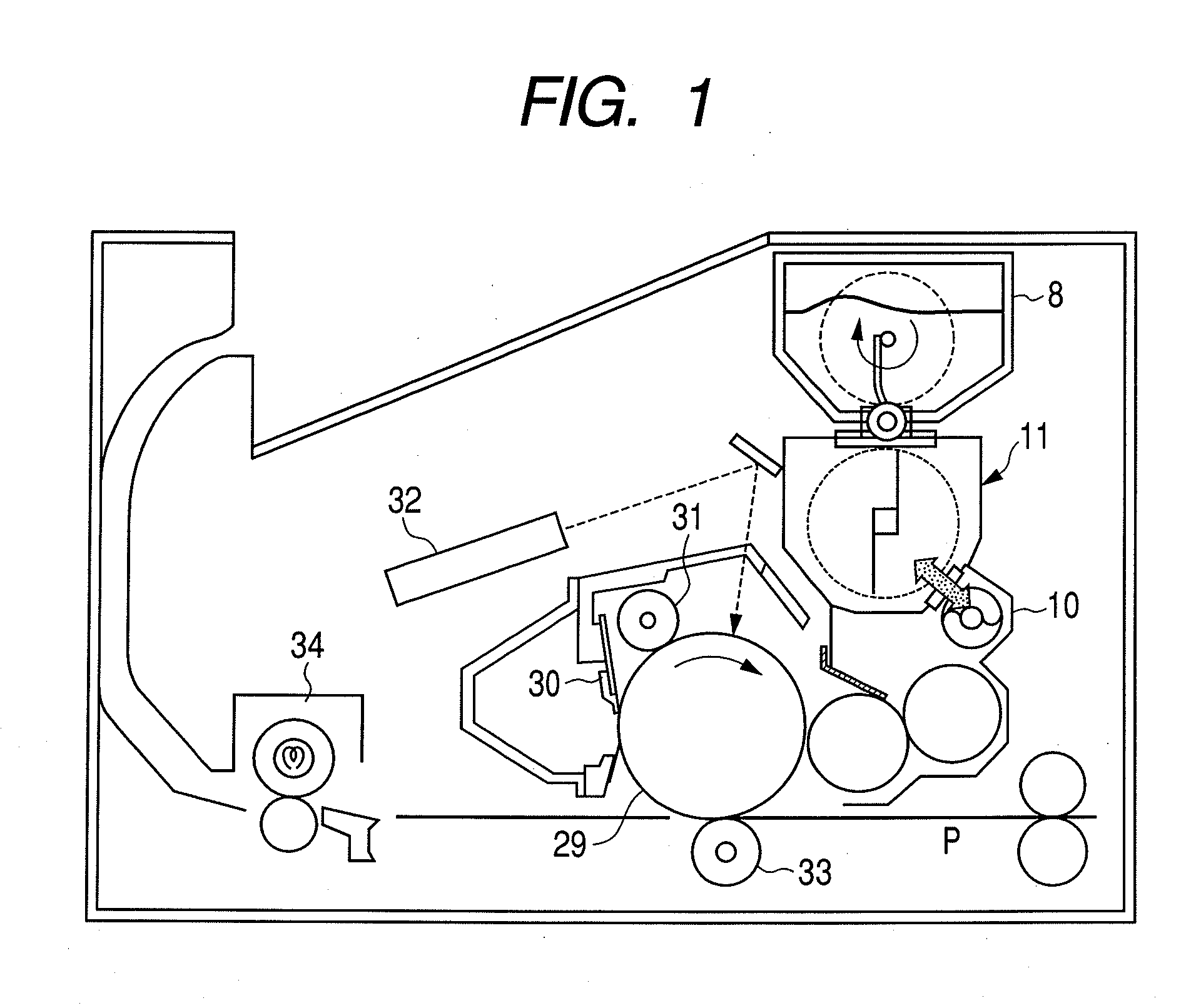
[0036]Hereinafter, exemplary embodiments of a developing apparatus according to the present invention will be described in detail with reference to the drawings. FIG. 1 illustrates one example of an image forming apparatus equipped with a developing apparatus of the present embodiment.

[0037](Image Forming Apparatus)

[0038]In a substantially central part of an image forming apparatus main body as illustrated in FIG. 1, for example, a drum-shaped electrophotographic photosensitive member 29 (hereinafter simply referred to as “photosensitive drum 29”) as an image bearing member is supported rotatably in a clockwise direction as indicated by the arrow in FIG. 1. When an operation of an image formation begins, the surface of the photosensitive drum 29 is electrostatically charged uniformly by a charging member 31, a laser scanner 32 as a laser irradiating unit serving as an exposure unit performs exposure according to image information on the charged drum surface, then an electrostatic la...


PUM


Abstract

A developing apparatus includes: an agitating chamber agitating a developer; a developing chamber provided with an inlet to which the developer is supplied from the agitating chamber and an outlet from which the developer is returned to the agitating chamber; a developer carrying member; a rotatable developer supplying member supplying the developer to the developer carrying member; a developer conveying member, provided above the center of rotation of the developer supplying member in the developing chamber, for conveying the developer in a longitudinal direction of the developer carrying member, wherein, in a vertical cross-sectional area of a region vertically above the center of rotation of the developer supplying member of the developing chamber, excluding a developer conveying region by the developer conveying member, a cross-sectional area S1 upstream in the developer conveying direction and a cross-sectional area S2 downstream in the developer conveying direction satisfy a relationship of S1<S2.

Description

BACKGROUND OF THE INVENTION[0001]1. Field of the Invention[0002]The present invention relates to a developing apparatus that can be used for an image forming apparatus, such as a copying machine, a facsimile machine, a printer and a combined copying machine. The developing apparatus can be provided in a cartridge detachably mountable to the main body of the image forming apparatus.[0003]2. Description of the Related Art[0004]Conventionally, a developing system using dual-component developer has been frequently used in general, but in recent years, there has been a growth in the use of developing apparatuses using mono-component developer that are simple in construction and advantageous also in running cost. Also, there is available a replenishing system for replenishing a developer (hereinafter simply referred to as “toner”) in order to maintain image quality satisfactory until it reaches the end of developer life. Even in this case, however, the use of the mono-component developer ...

Claims


Application Information

Patent Timeline
IPC IPC(8): G03G15/08
CPCG03G15/0822G03G2215/0852G03G2215/0838G03G2215/0827
Inventor IMAMURA, ISSEIYAMAGUCHI, SEIJI
Owner CANON KK
Learn More