Static eliminating device and image forming apparatus

An image and electro-optic technology, which is applied in the field of static elimination devices and image forming devices, can solve the problems of uneven distribution of static elimination light quantity, reduction of static elimination light throughput, etc.

Active Publication Date: 2013-12-04
KYOCERA DOCUMENT SOLUTIONS INC
View PDF5 Cites 1 Cited by
  • Summary
  • Abstract
  • Description
  • Claims
  • Application Information

AI Technical Summary

Problems solved by technology

However, since the neutralization light is easily blocked by the restriction protrusion, the throughput of the neutralization light decreases
As a result, there is a problem that the distribution of the amount of neutralizing light along the axial direction of the photoreceptor drum is not uniform.

Method used


Image

  • Static eliminating device and image forming apparatus
  • Static eliminating device and image forming apparatus
  • Static eliminating device and image forming apparatus

Examples


Embodiment 1

[0091] The restricting projection 150 of Example 1 is the first embodiment Figure 6 and Figure 7 In the example shown, the radius of the circle of the lower base (=circle with a large area=circle truncation of the protruding portion 156 on the base end side) is 1 mm, and the circle at the upper base of the protruding portion 151 on the distal end side (circle with a small area) has a radius of 0.5 mm. mm.

Embodiment 2

[0092] The restriction projection 150A of Example 2 is a second embodiment Figure 9 and Figure 10 In the example shown, the radius of the circle at the lower base (circle with a large area = the truncated circle of the base-side protrusion 156 ) is 1 mm, and the radius of the circle at the upper base of the distal-side protrusion 151A (circle with a small area) is 0.5 mm. .

[0093] The control protrusion 150Z of the comparative example is a conventional form Figure 8 In the example shown, the truncated circle has a radius of 1mm.

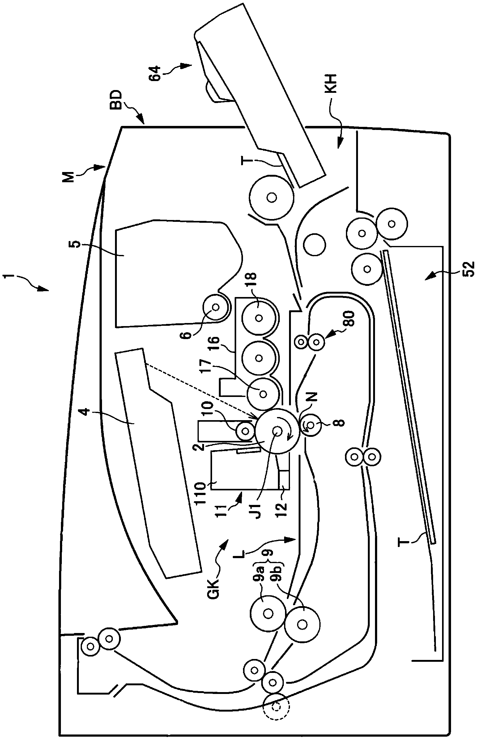
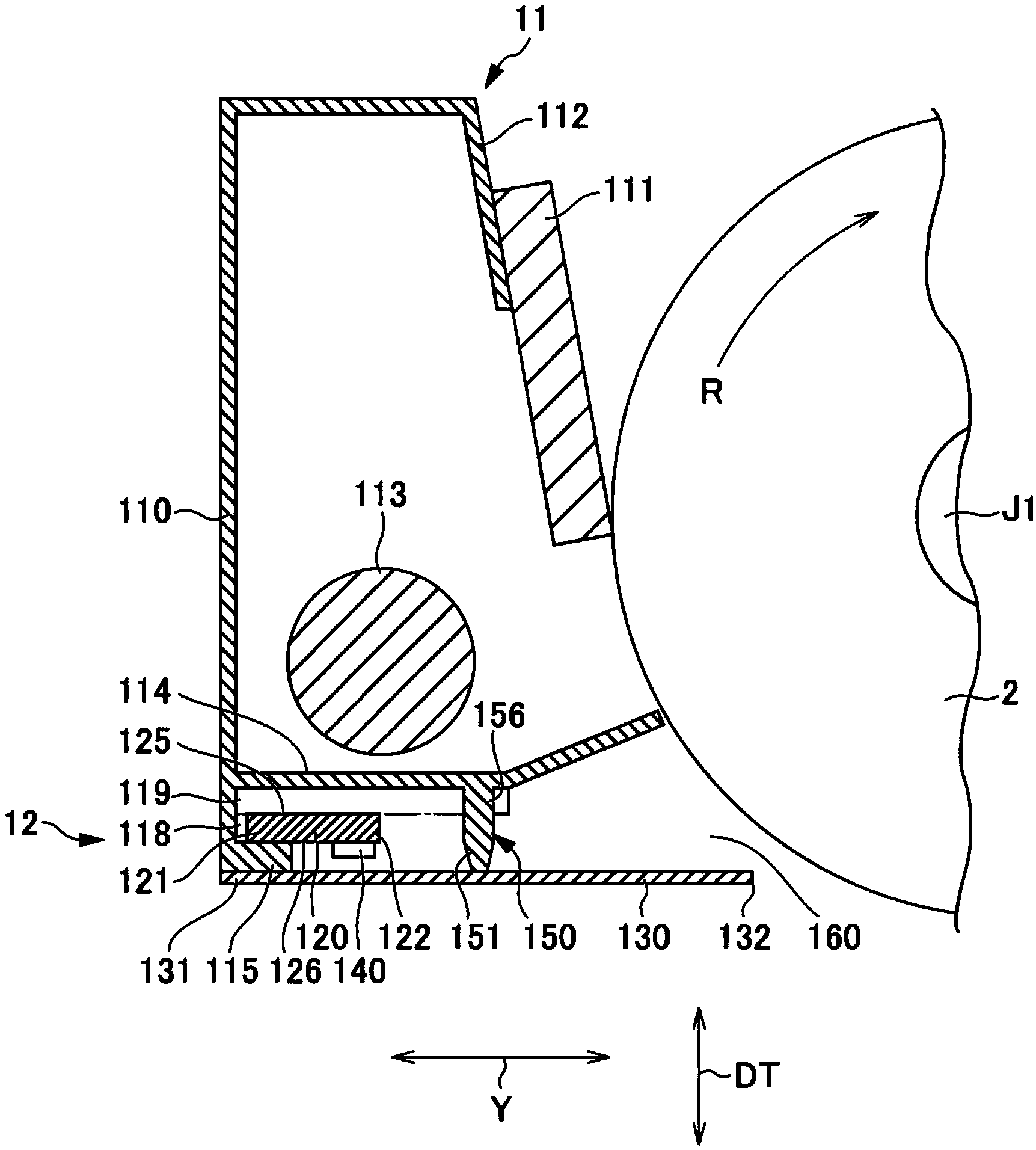
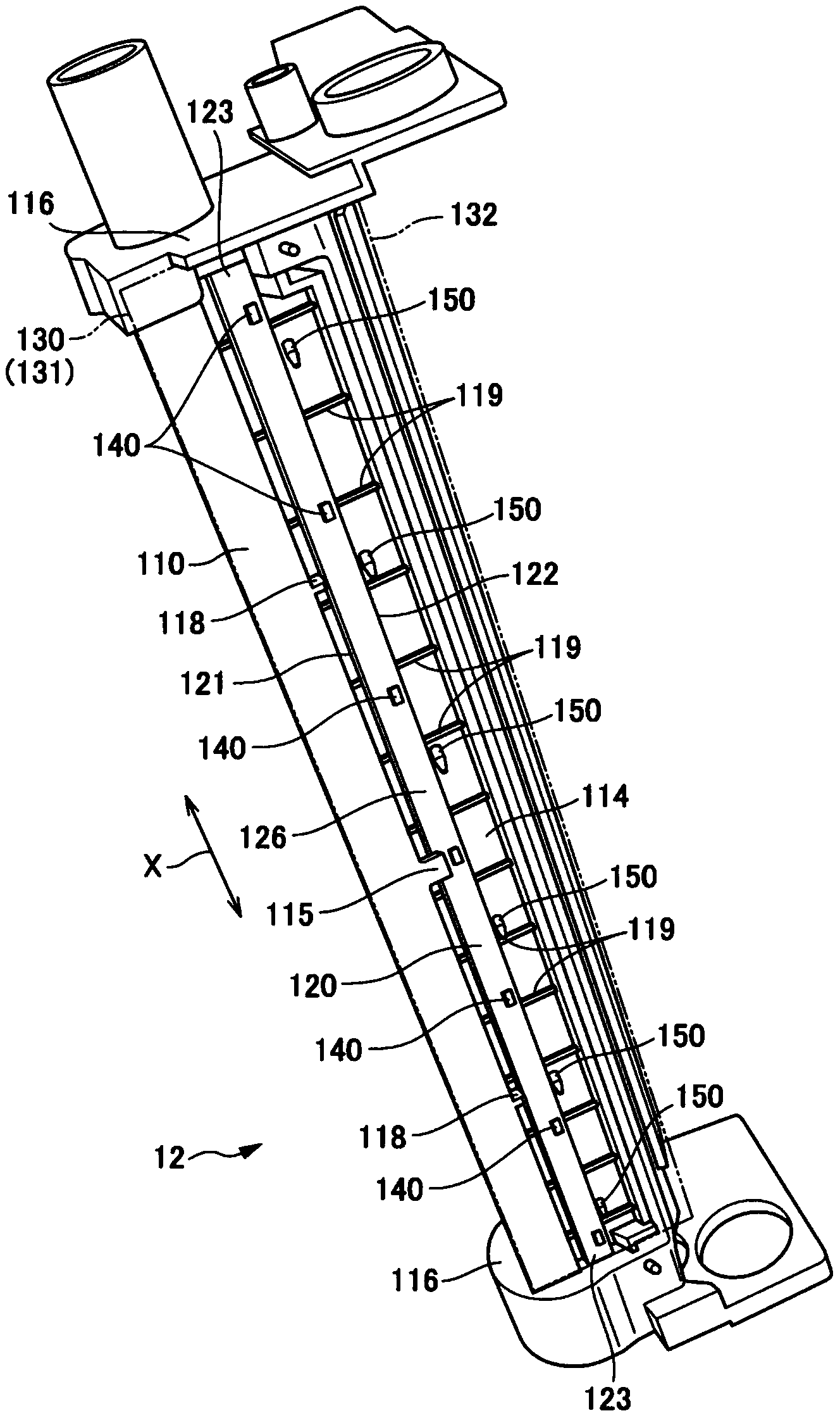
[0094] Additionally, if Figure 5 As shown, the distance L between the supporting positions of the pair of third end portions 123 of the substrate 120 is 240 mm. Such as Figure 6 As shown, the distance D1 from the LED 140 to the surface of the photoreceptor drum 2 is 18.6 mm. The width D2 of the opening portion 160 in the vertical direction (thickness direction of the spacer member 130 ) was 2.5 mm. As the LED 140 , an LED having a half-...


PUM


Abstract

A static eliminating device includes: a housing; a substrate mounted to the housing; a light-emitting part mounted on a mounting surface of the substrate; a partition member connected to the housing to cover the substrate and the light-emitting part and face a portion of the housing to which the substrate and the light-emitting part are mounted so that an opening facing the surface of the image carrier is formed in a light-emitting region across which light is delivered from the light-emitting part to the surface of the image carrier; and a restricting protrusion abutting at a distal end thereof against the partition member to support the partition member and restricting the position of the partition member to ensure the formation of the opening. A distal side portion of the restricting protrusion located within the light-emitting region has a tapered shape narrowing with approach toward the partition member.

Description

technical field [0001] The present invention relates to a static elimination device that eliminates static electricity on an image holder by irradiating the static elimination light to the image holder, and an electrophotographic image forming apparatus including the static elimination device. Background technique [0002] In an electrophotographic image forming apparatus, reduction in component costs and compactness of the apparatus housing are pursued. Furthermore, as the performance of the photoreceptor drum which is an image holder, the reduction of the exposure-stored image occurring on the surface of the photoreceptor drum is pursued. In order to reduce the generation of exposed memory images, it is necessary to irradiate the area of ​​the photoreceptor drum with deionizing light after the transfer to decharge the surface of the photoreceptor drum. [0003] Typically, the static eliminator is disposed between a drum cleaning device that removes toner and other deposit...

Claims


Application Information

Patent Timeline
Patent Type & Authority Applications(China)
IPC IPC(8): G03G21/08
CPCG03G21/08G03G21/06
Inventor 中井润太田克哉
Owner KYOCERA DOCUMENT SOLUTIONS INC
Why Eureka
Try Eureka