Cartridge and electrophotographic image forming apparatus

a technology of electrophotographic image and forming apparatus, which is applied in the direction of electrographic process apparatus, instruments, optics, etc., can solve the problems of affecting the downsizing of the electrophotographic image forming apparatus, and achieve the effect of reducing the downsizing of the electrophotographic image and increasing the operability

Inactive Publication Date: 2008-06-19
CANON KK
View PDF6 Cites 19 Cited by
  • Summary
  • Abstract
  • Description
  • Claims
  • Application Information

AI Technical Summary

Benefits of technology

[0006]Therefore, the present invention provides a cartridge and an electrophotographic image forming apparatus achieving downsizing of an electrophotographic image forming apparatus main body, and further achieving higher operability when dismounting and mounting the cartridge to the electrophotographic image forming apparatus main body.
[0007]In addition, the present invention provides a cartridge detachably mountable to an electrophotographic image forming apparatus main body for forming an image on a recording medium, the electrophotographic image forming apparatus main body having: a main body guide; a restraining unit provided movably with respect to the main body guide; and a main body abutting portion, the cartridge comprising: a frame; a guided portion protruded from the frame so as to be guided by the main body guide, and abutting on the restraining unit on a way the cartridge is being mounted to the image forming apparatus main body so as to be restrained from moving to a downstream side in a mounting direction; and a moving member provided movably with respect to the frame, abutting on the main body abutting portion so as to be moved to act on the restraining unit, and thereby moving the restraining unit on which the guided portion abuts to an allowable position of allowing the guided portion to move to the downstream side in the mounting direction.

Problems solved by technology

However, there are some cases where downsizing of an electrophotographic image forming apparatus is affected by the shape of the main body guide member.

Method used


Image

  • Cartridge and electrophotographic image forming apparatus
  • Cartridge and electrophotographic image forming apparatus
  • Cartridge and electrophotographic image forming apparatus

Examples


embodiment 1

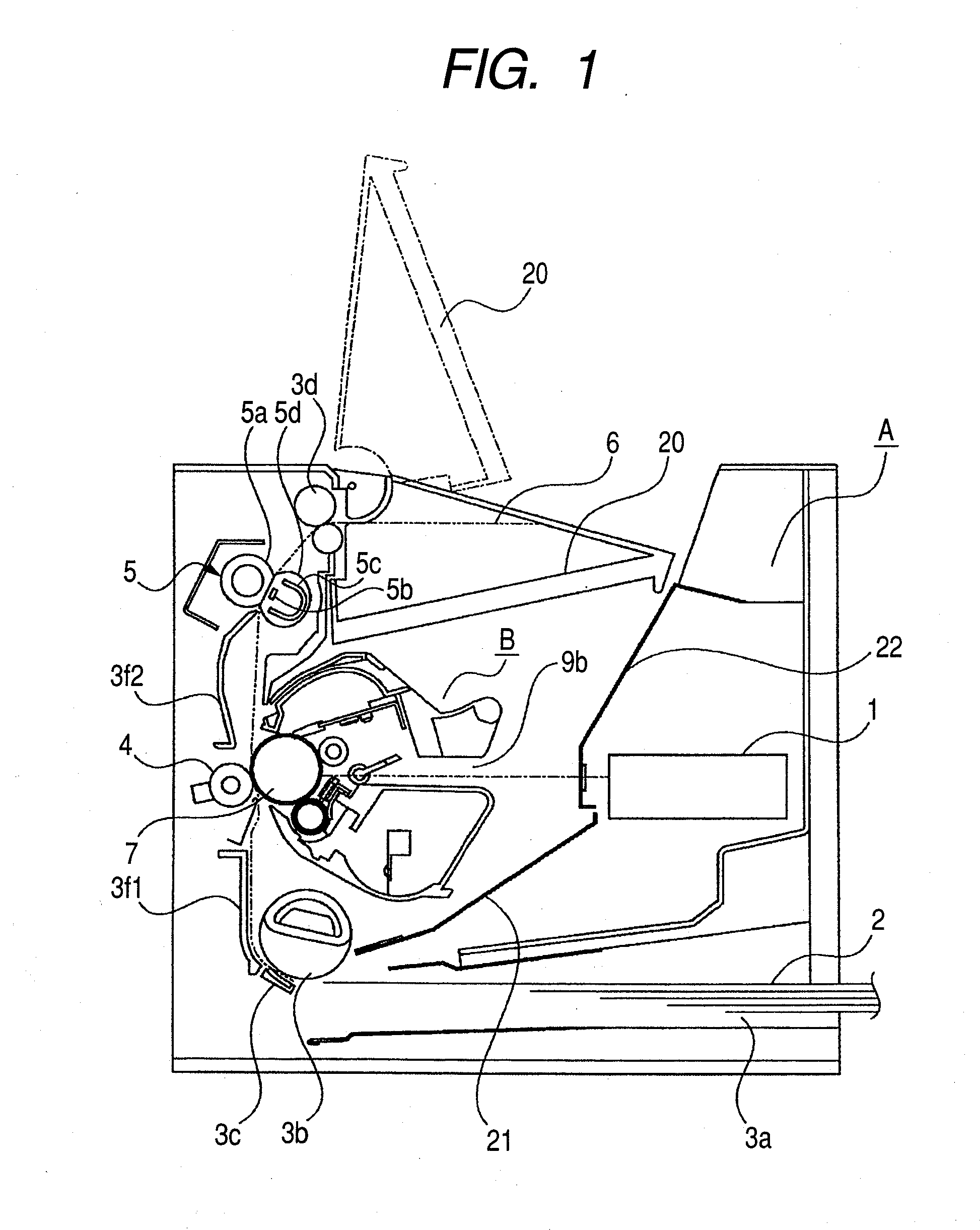
[0043]Hereinafter, a first exemplary embodiment according to the present invention will be described in detail referring to the accompanying drawings. The longitudinal direction of a process cartridge is the direction (a direction of the axis of rotation of a photosensitive drum or a direction substantially orthogonal to) intersecting the direction of mounting the process cartridge into an electrophotographic image forming apparatus main body. Furthermore, the left and right of the process cartridge is the left or the right as viewed along the direction of mounting the process cartridge into the electrophotographic image forming apparatus main body. In addition, the top face of the process cartridge is the face positioned above in the state in which the process cartridge is mounted in the electrophotographic image forming apparatus main body, and the bottom face is the face positioned below in that state.

[0044]First, the process cartridge and the electrophotograpic image forming app...

embodiment 2

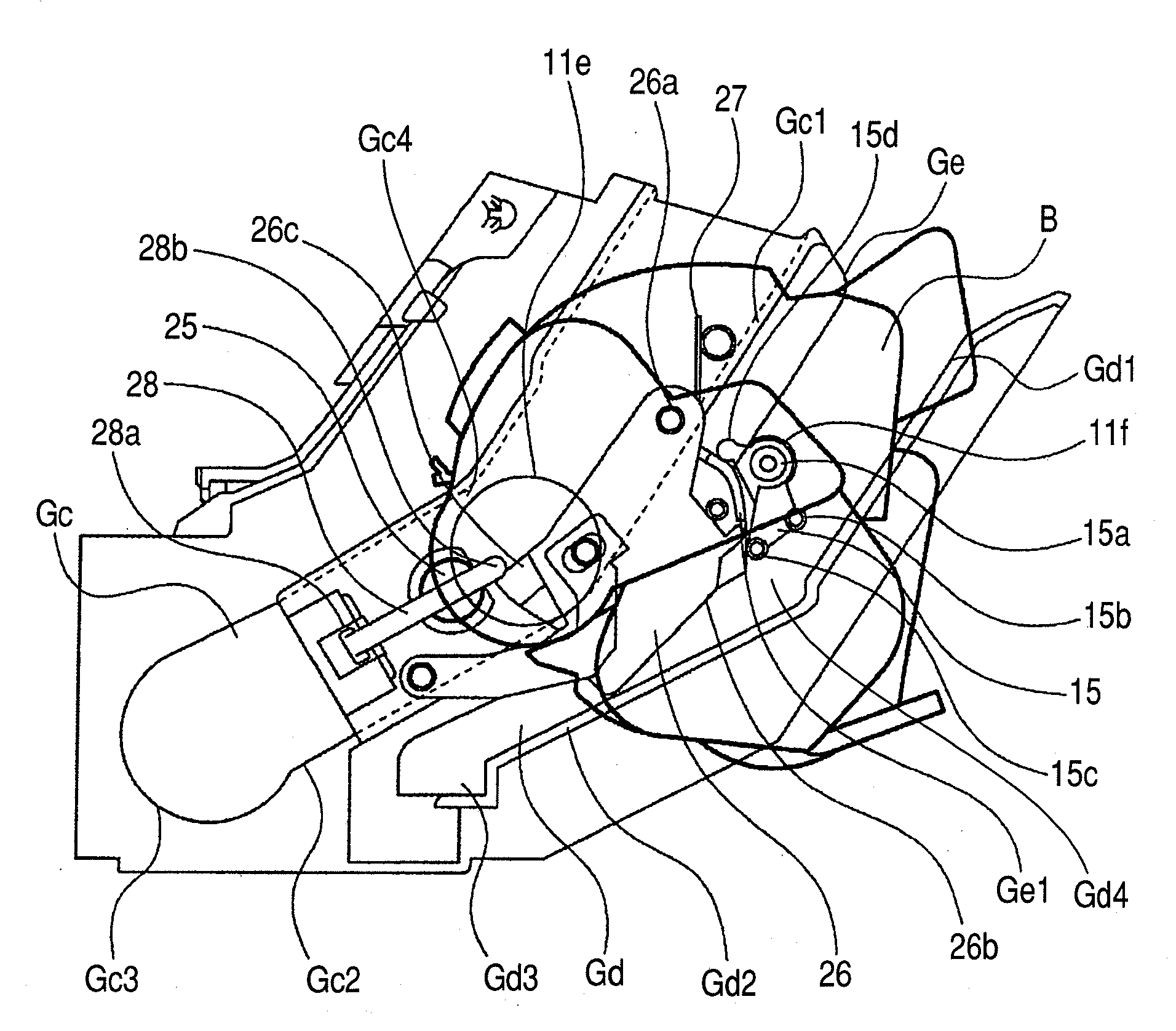
[0079]Now, a second embodiment according to the present invention will be described referring to the drawings. FIG. 21 is a schematic perspective view illustrating the side face of a cartridge. FIG. 22 is a schematic sectional view illustrating the construction of a guide portion between the cartridge and an image forming apparatus main body.

[0080]Although in the first embodiment, the second guided portion 11f is provided on the longitudinally outside of the cleaning frame 11d of the cartridge B, a moving member 15 may also serve as a second guided portion.

[0081]That is, as illustrated in FIGS. 21 and 22, it is constructed such that a cylindrical guided portion 15e is formed coaxially with a rotation center 15a of the moving member 15, and engaged with a guide groove Gd as a second main body guide of the apparatus main body A, to cause the cartridge B to be guided. In addition, a second guided portion on the longitudinally opposite side is of the same construction as well.

[0082]Due ...

embodiment 3

[0088]Now, a third embodiment according to the present invention will be described with reference to FIGS. 23 to 33.

[0089]The construction in an internal part of a process cartridge B is the same as that of the first embodiment, so that descriptions thereof will be omitted.

[0090](Construction of Mounting / Dismounting a Process Cartridge from an Apparatus Main Body)

[0091]A mounting construction of mounting a process cartridge (hereinafter referred to as a cartridge) B on an image forming apparatus main body A will be described with reference to FIGS. 23 to 26.

[0092]A bearing member 18c is attached to a cleaning frame 11d of the cartridge B. Furthermore, at the bearing member 18c, as a mounting guide onto the apparatus main body A, there are provided a first guided portion 18c1 of a cylindrical shape that is formed to be coaxial with the rotation axis of the photosensitive drum 7 and a second guided portion 18c2 as a rotation stopper. The second guided portion 18c2 determines the postu...


PUM


Abstract

A cartridge detachably mountable to an electrophotographic image forming apparatus main body for forming an image on a recording medium, the apparatus main body having: a main body guide; a restraining unit movable with respect to the main body guide; and a main body abutting portion, the cartridge including: a frame; a guided portion protruded from the frame so as to be guided by the main body guide, and abutting on the restraining unit on the way the cartridge is being mounted in the apparatus main body to be restrained from moving to the downstream side in a mounting direction; and a moving member movable with respect to the frame to abut on the main body abutting portion to be moved to act on the restraining unit to move the restraining unit to an allowable position in which the guided portion is allowed to move to the downstream side.

Description

BACKGROUND OF THE INVENTION[0001]1. Field of the Invention[0002]The present invention relates to a cartridge detachably mountable to an electrophotographic image forming apparatus for forming an image on a recording medium, and the electrophotographic image forming apparatus.[0003]2. Related Background Art[0004]Conventionally, in an electrophotographpic image forming apparatus employing an electrophotographic image forming process, employed is the system in which a process cartridge into which an electrophotographic photosensitive member and a process unit acting on the electrophotographic photosensitive member are integrally incorporated as a unit is detachably mountable to a main body of the image forming apparatus. Furthermore, in Japanese Patent Application Laid-Open No. 05-303242, known is the construction in which when mounting a process cartridge to an image forming apparatus main body, a guided portion of the process cartridge is guided by a main body guide, and thus the pro...

Claims


Application Information

Patent Timeline
Patent Type & Authority Applications(United States)
IPC IPC(8): G03G21/18
CPCG03G21/1853G03G2221/1884G03G2221/1684G03G2221/1654
Inventor HOSHI, NOBUHARUKARAKAMA, TOSHIYUKI
Owner CANON KK
Why Eureka
Try Eureka