Light diffuser

a light diffuser and light technology, applied in the field of headsets, can solve the problems of increasing difficulty in achieving the acoustic performance of the receiver and the microphone, affecting the sound quality of the receiver, and the size and weight of the headset,

Inactive Publication Date: 2008-07-10
APPLE INC
View PDF2 Cites 92 Cited by
  • Summary
  • Abstract
  • Description
  • Claims
  • Application Information

AI Technical Summary

Benefits of technology

[0017]In accordance with one embodiment of the present invention, a display system that includes a housing, at least one light source, a diffuser, and control circuitry is provided. The housing can have an internal wall and a signal indicator region. The at least one light source can be locate

Problems solved by technology

For example, the size and weight of headsets can be key issues because of how they typically mount to a user's ear.
A heavy or large headset can pull on a user's ear

Method used


Image

  • Light diffuser
  • Light diffuser
  • Light diffuser

Examples


Embodiment Construction

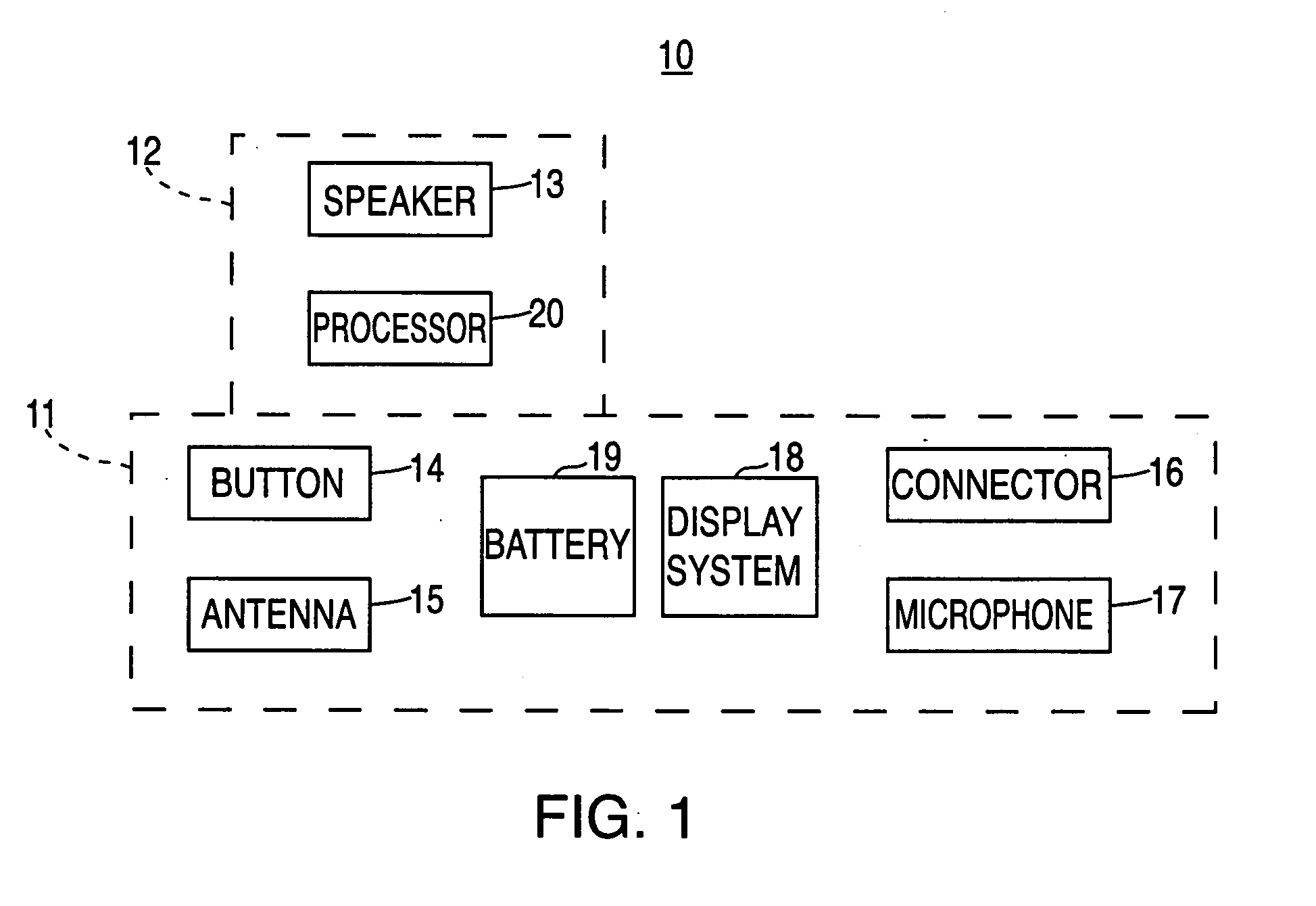
[0091]The present invention relates to headsets and methods for manufacturing the same. Headsets are communication devices that are worn on a user's head in order to allow hands free data and / or voice communication with a host device such as a computer, phone handset, cellular phone, an automobile and / or the like. Headsets can include one or more speakers (in proximity to one or both ears) for audio output and / or one or more microphones for audio input.

[0092]Headsets can come in a variety of form factors or shapes. In some cases, headsets can be embodied as an earpiece that serves as the primary support mechanism for wearing the headset. For example the headset may be supported on the head by an earpiece worn over or in the ear. Alternatively, the headset may be supported by a frame or band that fits on or over the user's head. The headset may include a fixed or movable boom that places the microphone closer to the user's mouth (wraps around the face). Alternatively, the headset may...


PUM


Abstract

A display system that includes a housing, at least one light source, a diffuser, and control circuitry is provided. The housing can have an internal wall and a signal indicator region. The at least one light source can be located within the housing. The diffuser can be disposed between the at least one light source and the internal wall. The control circuitry can be electrically coupled to and operable to cause the at least one light source to emit light that passes through the diffuser to the signal indicator region. A method for displaying signals in a headset including a signal indicator region is provided. The method can include emitting light from at least one LED. The method can include transmitting the light through a diffuser and onto the signal indicator region. The diffuser can include a substantially transparent substrate in which a plurality of translucent particles are embedded.

Description

CROSS-REFERENCE TO RELATED APPLICATIONS[0001]This application claims the benefit of certain copending, commonly assigned U.S. Provisional Patent Applications, namely, Ser. No. 60 / 878,852 filed on Jan. 5, 2007; Ser. No. 60 / 879,177 filed on Jan. 6, 2007; Ser. No. 60 / 879,193 filed on Jan. 6, 2007; Ser. No. 60 / 879,195 filed on Jan. 6, 2007; and Ser. No. ______ filed on Jun. 22, 2007 (Attorney Docket No. 104677-0102-001 (P5389USP1)), entitled “Single User Input Mechanism for Controlling Electronic Device Operations”; all of which are incorporated herein by reference.[0002]Commonly assigned DiFonzo et al. U.S. patent application Ser. No. 11 / 235,873, filed Sep. 26, 2005 (Attorney Docket No. P3794US1 / 119-0060US.1), entitled “Electromagnetic Connector for Electronic Device” is hereby incorporated by reference in its entirety.[0003]Commonly assigned Rohrbach et al. U.S. patent application Ser. No. 11 / 235,875, filed Sep. 26, 2005 (Attorney Docket No. P3593US1 / 119-0060US), entitled “Magnetic Co...

Claims


Application Information

Patent Timeline
IPC IPC(8): H04R25/00G08B5/00G08B5/22
CPCH01R13/2428H04R5/033H01R13/64H01R13/7039H01R29/00H01R43/26H04M1/0262H04M1/0274H04M1/0277H04M1/05H04M1/6058H04M1/6066H04M2250/02H04R1/1016H04R1/1041H04R1/1058H01R13/6205H01R13/703H01R27/02H04M1/60Y02D30/70
Inventor HANKEY, M. EVANSSANFORD, EMERY A.LIM, WAY CHET
Owner APPLE INC
Why Eureka
Try Eureka