
Lubricant applicator, process cartridge and image forming apparatus including the same

a technology of lubricant applicator and process cartridge, which is applied in the direction of manual lubrication, machines/engines, instruments, etc., can solve the problems of affecting the lubricant supply of the entire surface of the photoreceptor, the inability to remove or clean the residual toner from the photoreceptor, and the withdrawal of such a toner

Active Publication Date: 2008-07-17
RICOH KK
View PDF13 Cites 8 Cited by
  • Summary
  • Abstract
  • Description
  • Claims
  • Application Information

AI Technical Summary

Benefits of technology

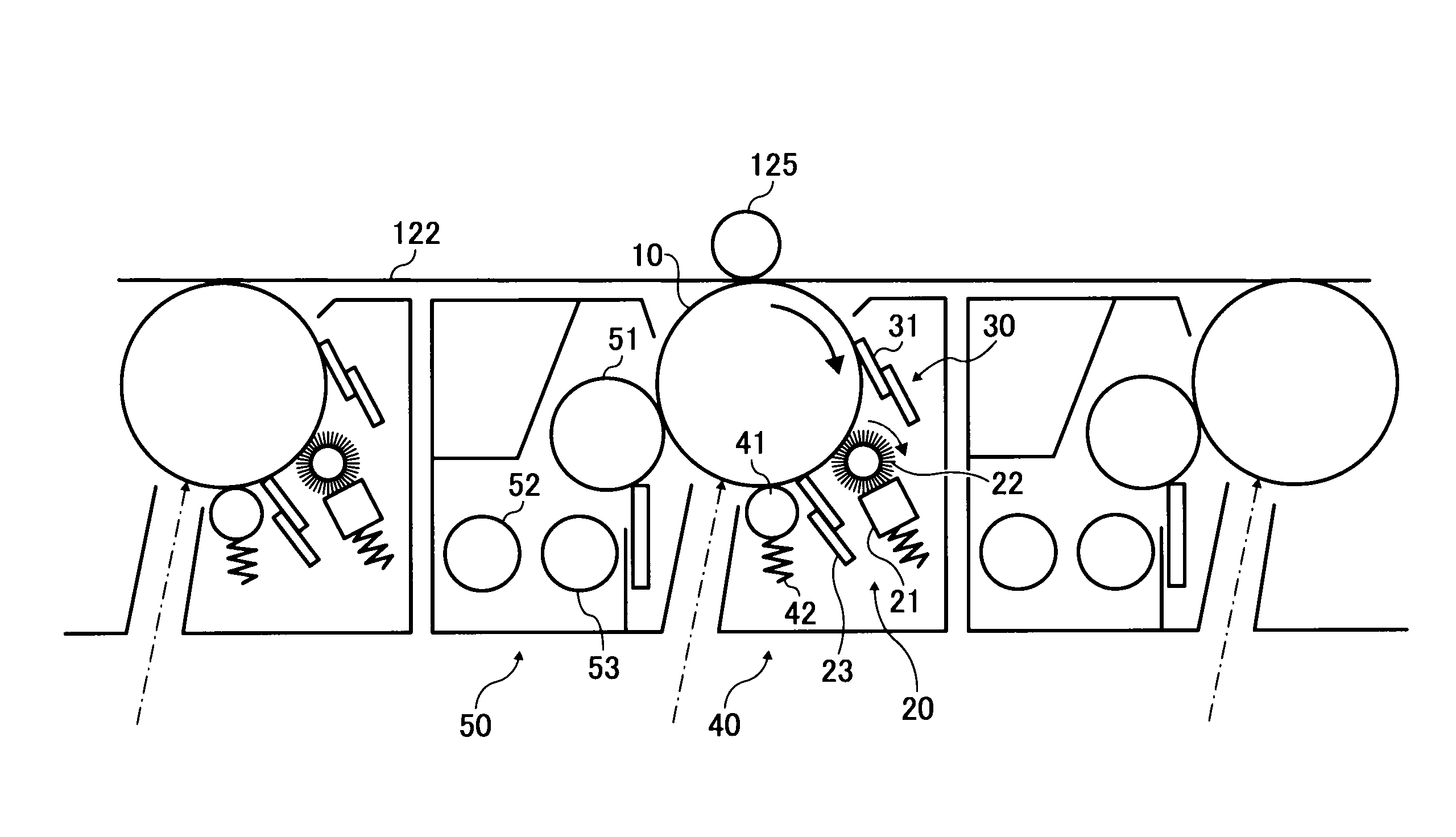
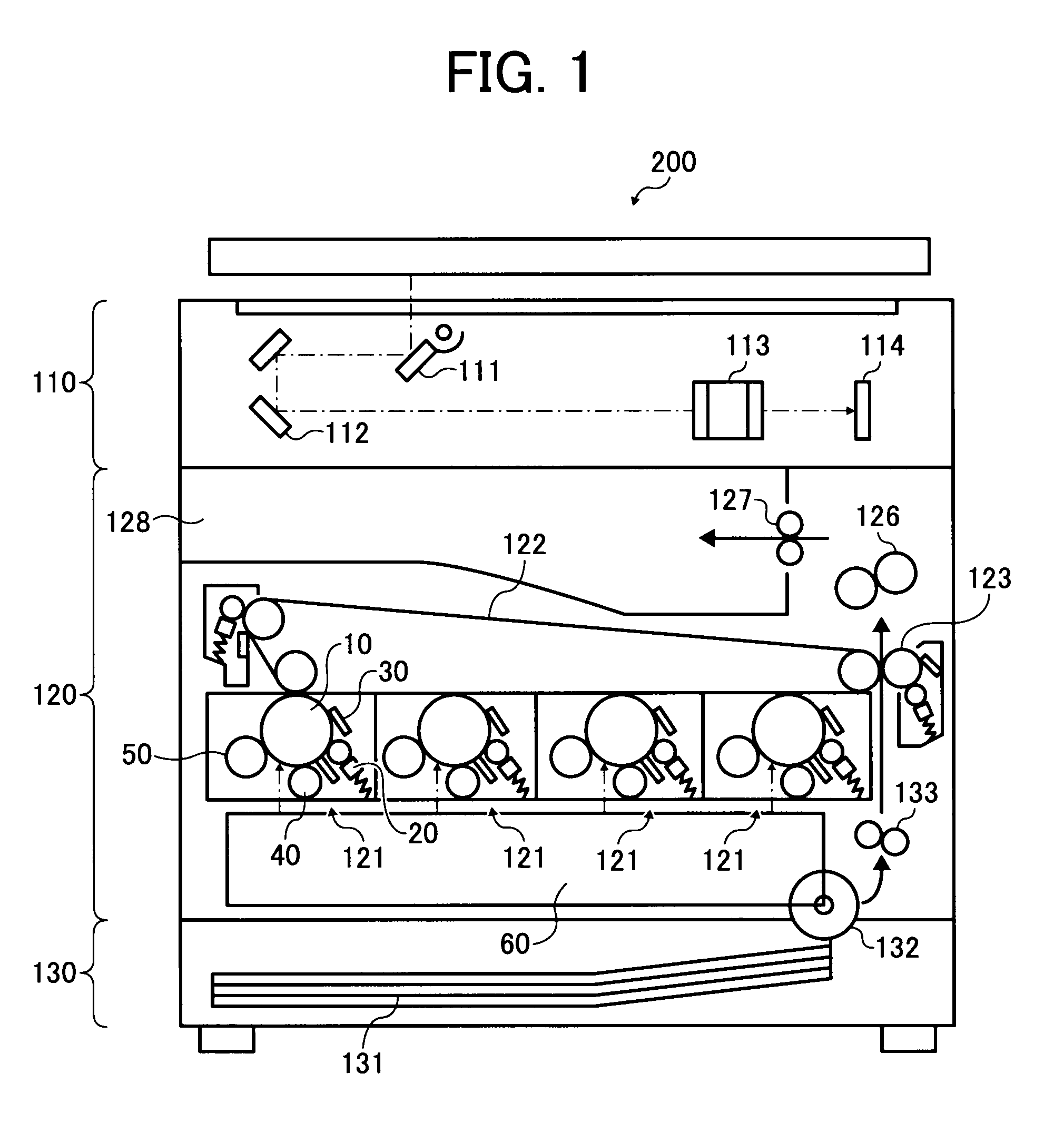
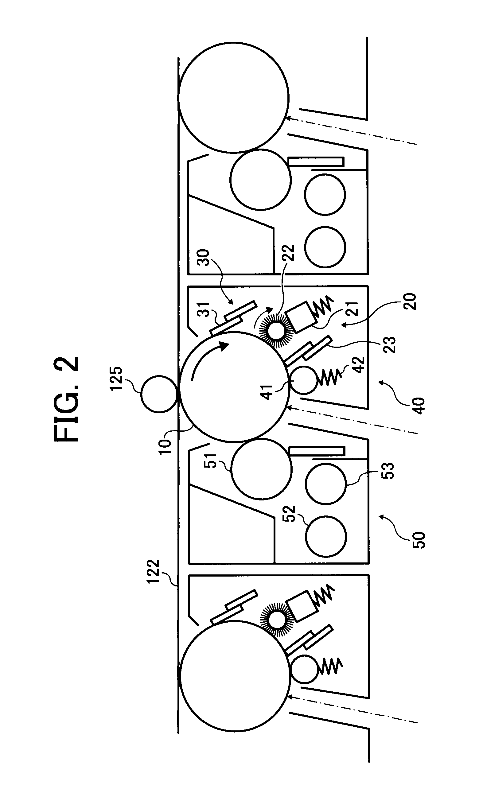
[0027]In one exemplary embodiment, a lubricant applicator includes a solid lubricant, a lubricant retainer, a lubricant holder, a lubricant application mechanism, a pressure mechanism, and a friction resistance reduction mechanism. The lubricant retainer holds the solid lubricant. The lubricant holder stores the solid lubricant and the lubricant retainer. The lubricant application mechanism ap...

Problems solved by technology

On the other hand, there is a drawback to such a toner.
That is, the small size of the toner particles makes removal or cleaning of the residual toner from the photoreceptor difficult.
Consequently, it is difficult to stably supply the lubricant to an entire surface of the photoreceptor.
However, when the amount supplied becomes excessive, the excess lubricant may contaminate nearby devices such as a developing unit.
Consequently, a charging amount of the toner may not be properly regulated.
However, the above-described related arts do not indicate ways to improve sliding between a lubricant support member for supporting the lubricant in the lubricant applicator and a lubricant holder for storing the lubricant.
Consequently, there is such a problem that the solid lubricant cannot be pressed against the lubricant application brush, and thus the amount of the lubricant applied to the image carrier surface fluctuates.
When the amount of the lubricant applied fluctuates and is excessive, the nearby charging unit or other devices disposed nearby may easily be contaminated.
On the other hand, when the applied amount of the lubricant is inadequate, the toner adheres to the image carrier surface and a phenomenon called filming may easily occur.

Method used


Image

  • Lubricant applicator, process cartridge and image forming apparatus including the same
  • Lubricant applicator, process cartridge and image forming apparatus including the same
  • Lubricant applicator, process cartridge and image forming apparatus including the same

Examples


Embodiment Construction

[0039]It will be understood that if an element or layer is referred to as being “on,”“against,”“connected to” or “coupled to” another element or layer, then it can be directly on, against connected or coupled to the other element or layer, or intervening elements or layers may be present.

[0040]In contrast, if an element is referred to as being “directly on”, “directly connected to” or “directly coupled to” another element or layer, then there are no intervening elements or layers present. Like numbers refer to like elements throughout.

[0041]As used herein, the term “and / or” includes any and all combinations of one or more of the associated listed items.

[0042]Spatially relative terms, such as “beneath”, “below”, “lower”, “above”, “upper” and the like, may be used herein for ease of description to describe one element or feature's relationship to another element(s) or feature(s) as illustrated in the figures.

[0043]It will be understood that the spatially relative terms are intended to...


PUM


Abstract

An image forming apparatus includes a lubricant applicator and a process cartridge using the same. The lubricant applicator includes a solid lubricant, a lubricant retainer, a lubricant holder, a lubricant application mechanism, a pressure mechanism, a friction resistance reduction mechanism. The lubricant retainer holds the solid lubricant. The lubricant holder stores the solid lubricant and the lubricant retainer. The lubricant application mechanism applies the solid lubricant to an object. The pressure mechanism is provided between the lubricant retainer and the lubricant holder, and presses the lubricant retainer to push the solid lubricant from the lubricant holder. The friction resistance reduction mechanism is disposed at a position where the lubricant retainer and the lubricant holder come into contact in a frictionally sliding manner. The friction resistance reduction mechanism includes a protrusion provided on at least one of a surface of the lubricant retainer and an inner wall of the lubricant holder.

Description

CROSS-REFERENCE TO RELATED APPLICATIONS[0001]The present patent application is based on and claims priority under 35 U.S.C. §119 upon Japanese Patent Application No. 2007-006557 filed on Jan, 16, 2007 in the Japan Patent Office, the entire contents of which are hereby incorporated herein by reference.BACKGROUND OF THE INVENTION[0002]1. Field of the Invention[0003]Exemplary aspects of the present invention generally relate to an image forming apparatus, and more particularly, to an image forming apparatus that includes a lubricant applicator and a process cartridge using the same.[0004]2. Description of the Background Art[0005]An image forming process performed by an image forming apparatus using an electrophotographic method includes forming an electrostatic latent image on a photoreceptor serving as an image carrier through photoconductive development and adhering toner particles of colors corresponding to the electrostatic latent image using electrostatic force.[0006]Such an elect...

Claims


Application Information

Patent Timeline
IPC IPC(8): G03G21/00F16N7/00
CPCG03G21/00F16N7/24
Inventor HARADA, HIROOMI
Owner RICOH KK
Learn More