Automated test tube cap removal apparatus

a test tube and cap removal technology, applied in the direction of instruments, chemical methods analysis, analysis using chemical indicators, etc., can solve the problem of low cap removal efficiency

Active Publication Date: 2008-07-17
IDS CO LTD
View PDF4 Cites 61 Cited by
  • Summary
  • Abstract
  • Description
  • Claims
  • Application Information

AI Technical Summary

Benefits of technology

[0013]According to an aspect of the invention, an automated test tube cap removal apparatus comprises, a cap remover having a cap removing position for a test tube which contains a specimen, a test tube rack which holds a plurality of capped test tubes upright in a row and loads the test tubes into the cap removing position, a clamping mechanism which is disposed in the cap removing position and clamps the plurality of test tubes in the test tube rack, and a cap removal unit disposed in the cap removing position and configured to move upward to remove caps from some of a plurality of test tubes held in the test tube rack in a manner such that the caps are simultaneously supported by engagement and then move upward to remove caps from the remaining test tubes in a manner such that the caps are simultaneously supported by engagement. The cap removal unit includes a pair of engaging members which are capable of advance and retreat with respect to the caps and laterally clamp each cap when advanced, a lift mechanism which raises the pair of engaging members while alternately moving the engaging members upward, thereby removing the cap from each test tube, and a cap guide member which separates the cap from the engaging members and guides the cap for dropping when the engaging members retract from the cap after the cap removal.

Problems solved by technology

Thus, the efficiency of cap removal is low.

Method used


Image

  • Automated test tube cap removal apparatus
  • Automated test tube cap removal apparatus
  • Automated test tube cap removal apparatus

Examples


Embodiment Construction

[0037]An embodiment of this invention will now be described with reference to the accompanying drawings.

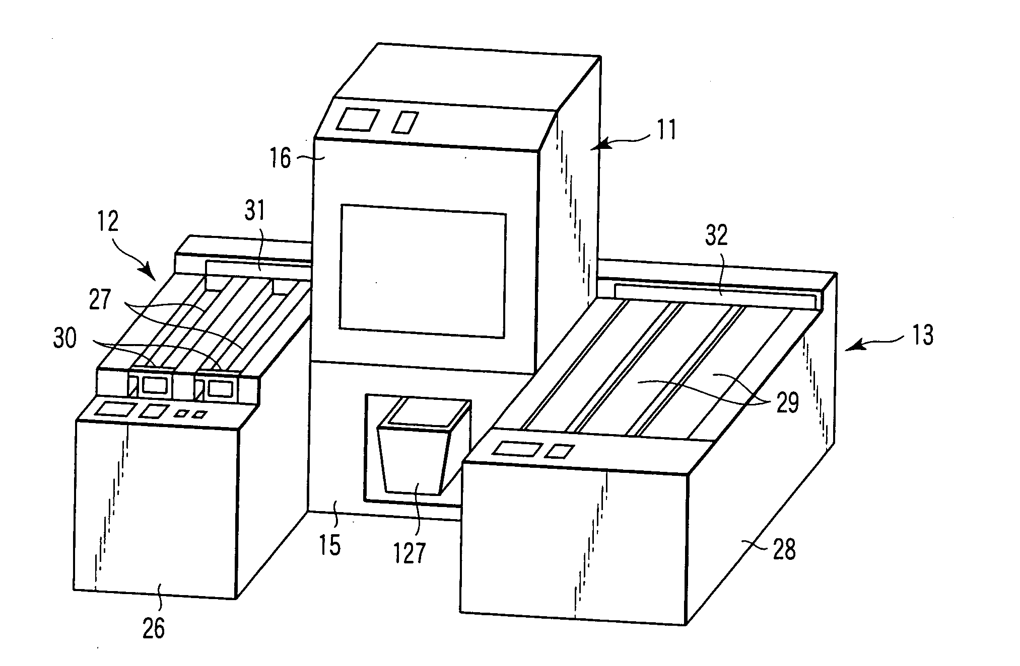
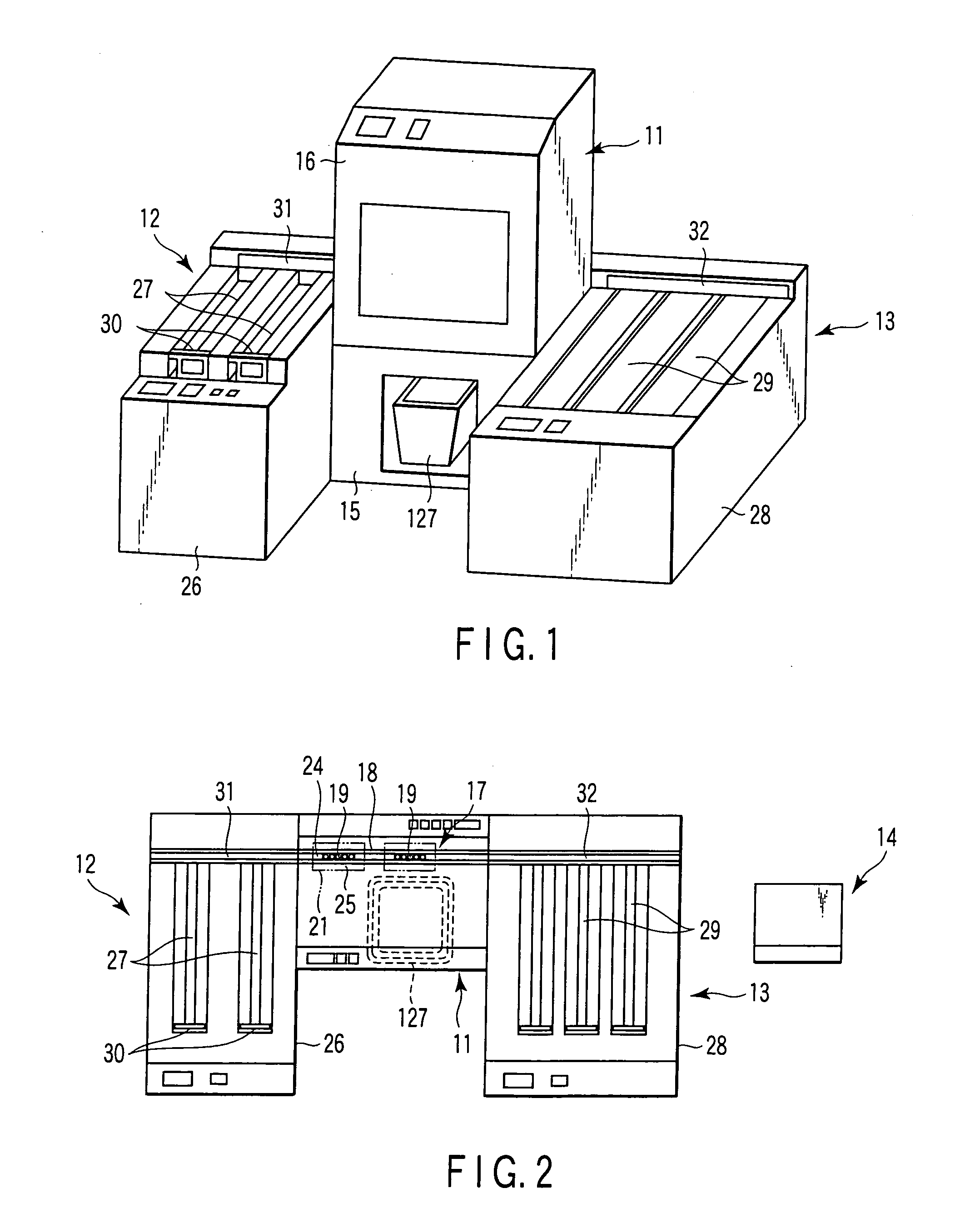
[0038]FIGS. 1 and 2 are a perspective view and a plan view, respectively, of an automated test tube cap removal apparatus. As shown in FIGS. 1 and 2, a cap remover 11 is provided in the central part of the apparatus. A start unit 12 for use as a test tube rack loading unit is set on the left-hand side of the cap remover 11, and a stocker unit 13 on the right-hand side. Further, a control unit 14 with a CPU is set near the start unit 12.

[0039]In the cap remover 11, a storage box 16 is disposed on top of a base 15, and a cap removal mechanism 17 (mentioned later) is located in the box 16. A rack conveying path 18 is provided at the rear part of the box 16. The conveying path 18 conveys test tube racks 19 that hold test tubes 20.

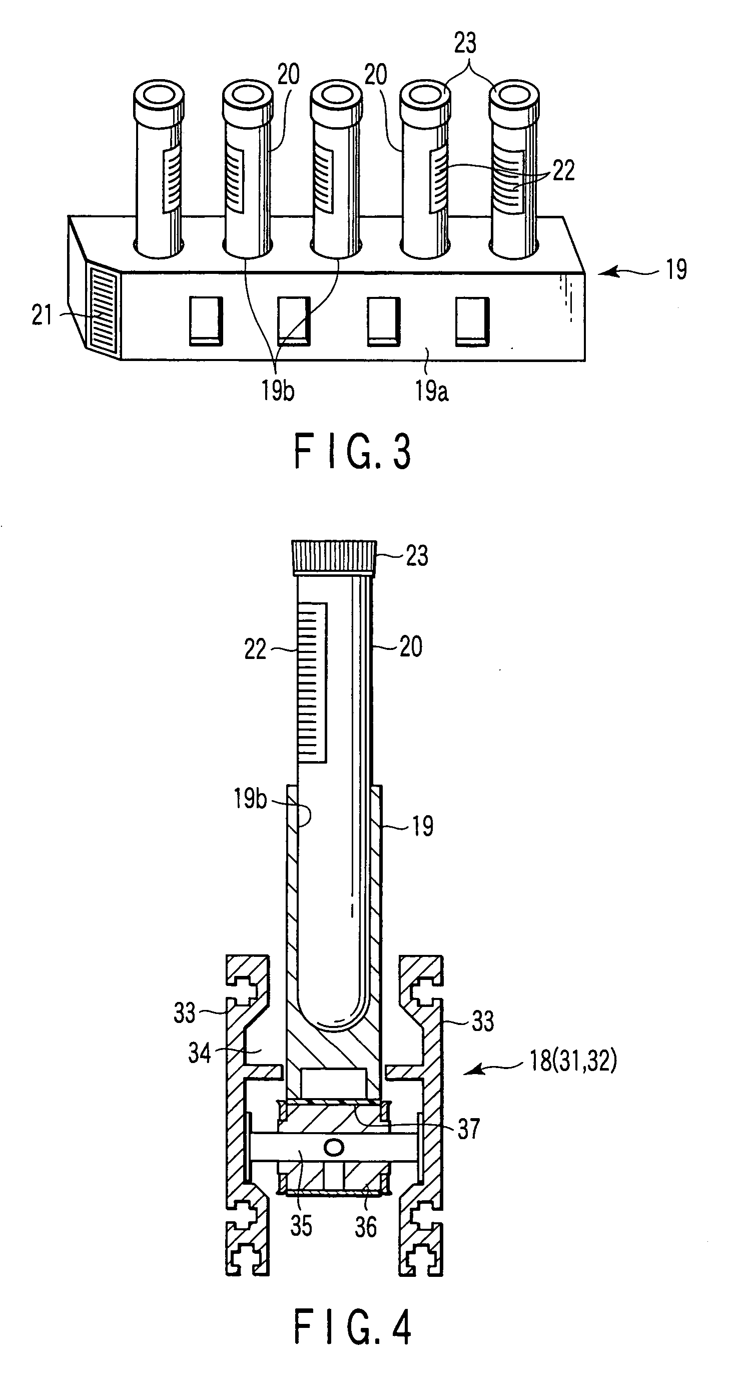
[0040]As shown in FIG. 3, each test tube rack 19 can hold a plurality of test tubes 20, five test tubes in a row, in an upright state. Specifically, the rack...


PUM

PropertyMeasurementUnit
sizeaaaaaaaaaa
sizesaaaaaaaaaa
diametersaaaaaaaaaa

Abstract

A automated test tube cap removal apparatus includes, a cap remover, a test tube rack which holds a plurality of capped test tubes upright in a row, a clamping mechanism which is disposed in the cap removing position and clamps the plurality of test tubes, and a cap removal unit disposed in the cap removing position and configured to move upward to remove caps from some of a plurality of test tubes and move upward to remove caps from the remaining test tubes. The cap removal unit includes engaging members which are capable of advance and retreat with respect to the caps and clamp each cap, a lift mechanism which raises the engaging members while alternately moving the engaging members upward, thereby removing the cap from each test tube, a cap guide member which separates the cap and guides the cap for dropping.

Description

CROSS-REFERENCE TO RELATED APPLICATIONS[0001]This application is based upon and claims the benefit of priority from prior Japanese Patent Application No. 2007-006029, filed Jan. 15, 2007, the entire contents of which are incorporated herein by reference.BACKGROUND OF THE INVENTION[0002]1. Field of the Invention[0003]This invention relates to an automated test tube cap removal apparatus for automatically removing caps from test tubes that contain a specimen, such as blood.[0004]2. Description of the Related Art[0005]In a known apparatus for removing caps from test tubes, as described in Jpn. Pat. Appln. KOKAI Publication No. 5-228379, for example, the cap of each test tube is supported by engagement with the distal end portion of a drawing arm in a manner such that the test tubes are held one by one by a test tube retaining member. Then, the drawing arm is raised in a cap drawing direction to automatically draw the cap from the test tube by actuating a lift cylinder with the cap supp...

Claims


Application Information

Patent Timeline
Patent Type & Authority Applications(United States)
IPC IPC(8): B01L9/06B01L99/00B67B7/02G01N35/02
CPCB67B7/02G01N2035/0405Y10T436/11Y10T436/114165Y10T436/113332G01N2035/041B01L9/00B01L2300/042
Inventor ITOH, TERUAKI
Owner IDS CO LTD
Why Eureka
Try Eureka