Surgical tray corner protector

Active Publication Date: 2008-07-31
VELMED
View PDF56 Cites 2 Cited by
  • Summary
  • Abstract
  • Description
  • Claims
  • Application Information

AI Technical Summary

Benefits of technology

[0005]Accordingly, the above-noted shortcomings of the prior art are addressed by the present invention, which provides a surgical tray corner protector t

Problems solved by technology

Unfortunately, after the sterilization process has taken place, it is often discovered that the feet of the trays have punctured through the sterile wrap, as shown in FIG. 2, causing the trays and instruments contained therein to be contaminated.
If a surgical instrument tray

Method used


Image

  • Surgical tray corner protector
  • Surgical tray corner protector
  • Surgical tray corner protector

Examples


Embodiment Construction

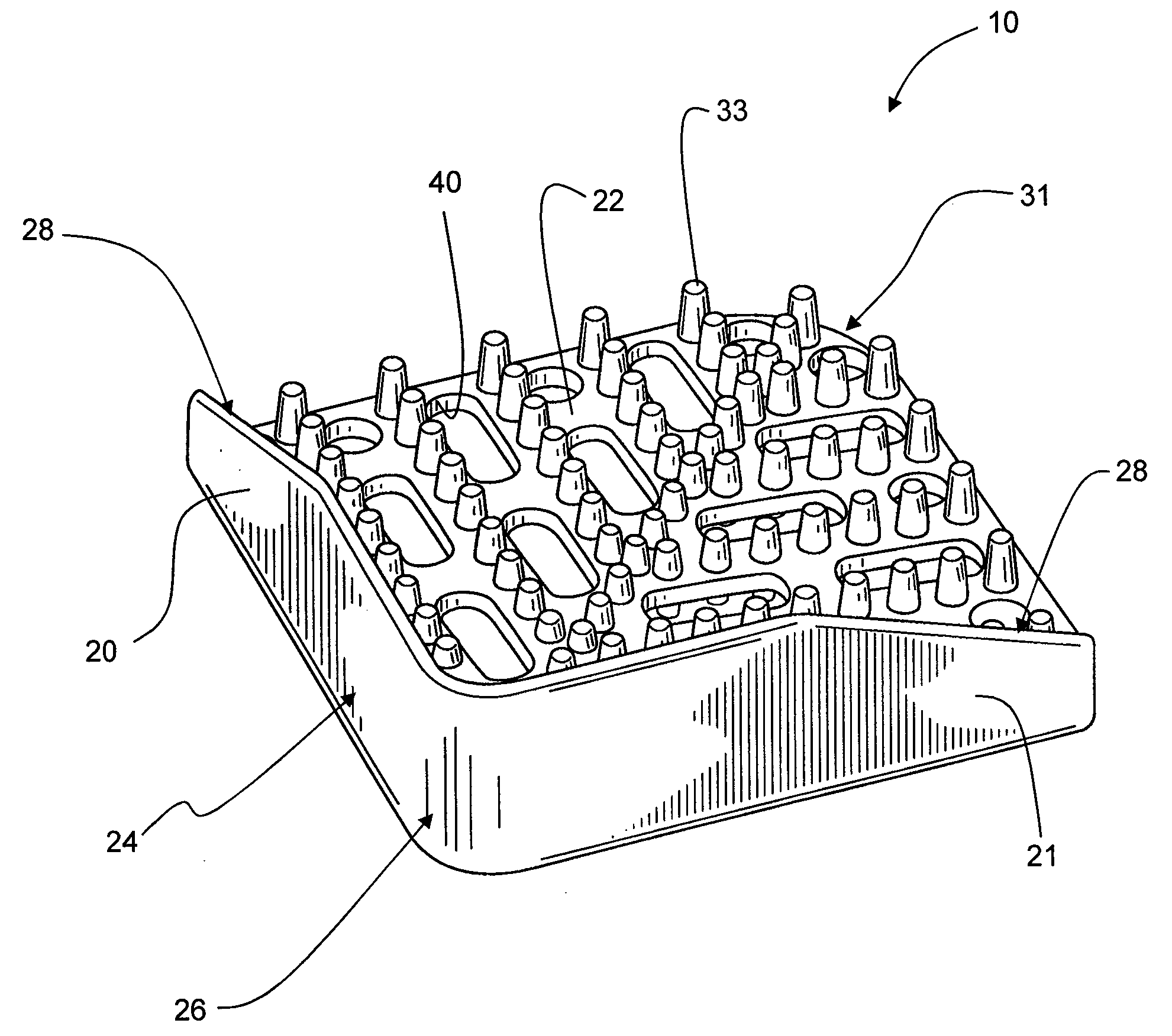
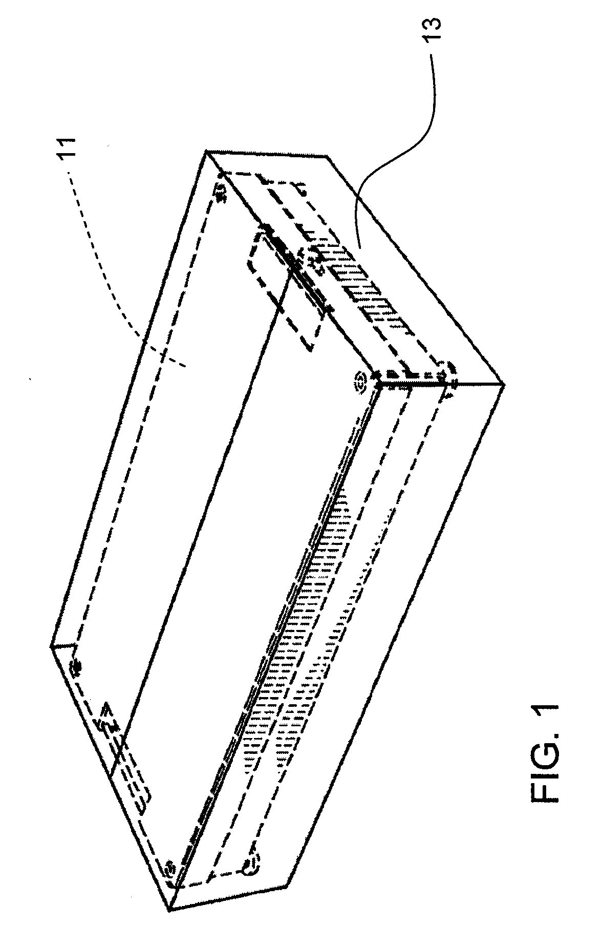
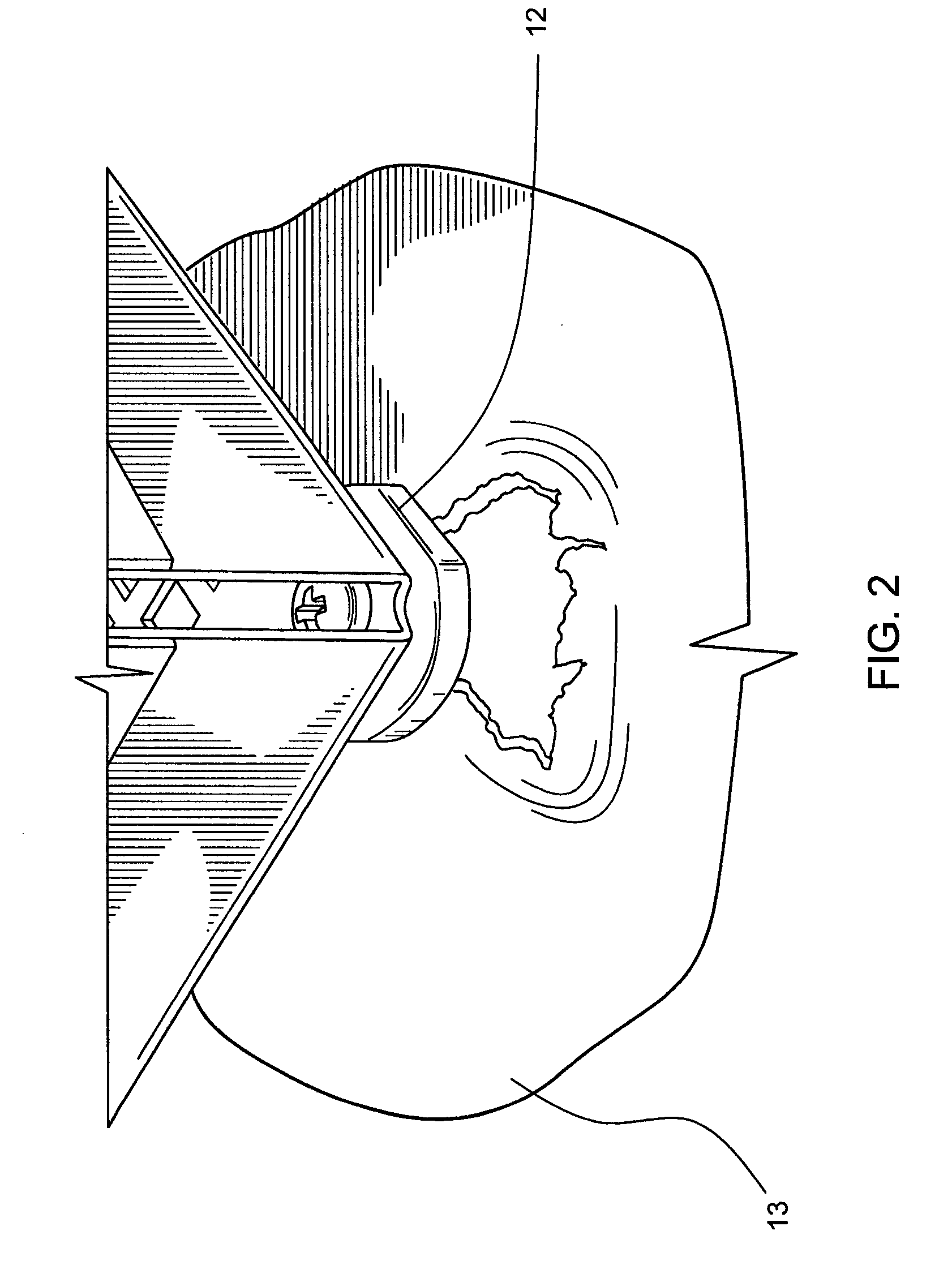
[0034]Referring now specifically to the drawings, a surgical tray corner protector according to an embodiment of the invention is illustrated in FIG. 3 and shown generally at reference numeral 10. The corner protector 10 is designed to be placed on a corner of a surgical tray 11 between a foot 12 of the tray 11 and a sterile wrap 13. The corner protector 10 prevents a foot 12 from puncturing through the sterile wrap 13 as shown in FIG. 2 while allowing a sterilization agent to circulate around the foot 12 and between the sterile wrap 13 and corner protector 10.

[0035]Referring to FIGS. 4-10, the corner protector 10 includes a pair of sides. 20 and 21 extending upwardly from a base 22. The sides 20 and 21 create a soft barrier between sharp corner edges 23 of the tray 11 and the sterile wrap 13 to prevent tearing of the sterile wrap 13. The sides 20 and 21 also allow the corner protector 10 to be used with straight edge or rounded edge surgical trays, enhance stability of the corner p...


PUM


Abstract

A corner protector for use with a surgical tray includes a base, at least one side extending from the base, and at least one aperture extending through the base. The at least one aperture allows a medium to pass therethrough. The corner protector further includes at least one stud extending from a major surface of the corner protector such that when the corner protector is positioned against a surgical tray, a channel is created between the corner protector and the surgical tray.

Description

TECHNICAL FIELD AND BACKGROUND OF THE INVENTION[0001]This application claims the benefit of Provisional Application No. 60 / 898,046 filed on Jan. 29, 2007.[0002]The present invention relates to the field of corner protectors. In particular, the invention relates to corner protectors for use with surgical trays.[0003]Surgical trays are used to organize, sterilize, and carry surgical instruments into an operating room for use by a surgeon. Because the surgical trays and instruments carry pathogens, the trays and instruments must be sterilized prior to being placed in the operating room. This is done by placing the instruments in the trays, wrapping the trays in sterile wraps, as shown in FIG. 1, and placing the wrapped trays in a sterilization chamber where a sterilization agent such as steam, gas, or plasma is used to sterilize the trays and instruments. The wrapped trays are then carried to the operating room for use.[0004]Unfortunately, after the sterilization process has taken plac...

Claims


Application Information

Patent Timeline
IPC IPC(8): B65D1/34
CPCA61B19/0271A61B19/026A61B50/30A61B50/33B65D81/053
Inventor LAVELLE, RICHARD M.
Owner VELMED
Why Eureka
Try Eureka