Heated dental pliers

a technology of pliers and pliers, which is applied in the field of tools, can solve the problems of not being able to accurately control the temperature, and being dangerous to patients and/or dentists

Inactive Publication Date: 2008-08-14
NEVIN DONALD
View PDF9 Cites 0 Cited by
  • Summary
  • Abstract
  • Description
  • Claims
  • Application Information

AI Technical Summary

Problems solved by technology

However, heating the pliers in that fashion does not permit the accurate control of the temperature and may therefore be dangerous to the patient and / or the dentist.

Method used


Image

  • Heated dental pliers
  • Heated dental pliers
  • Heated dental pliers

Examples


Embodiment Construction

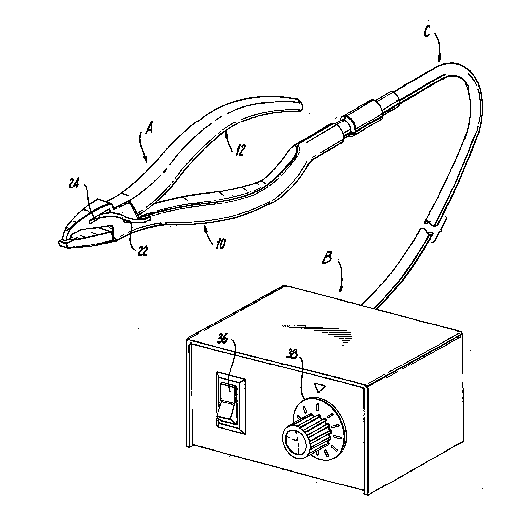
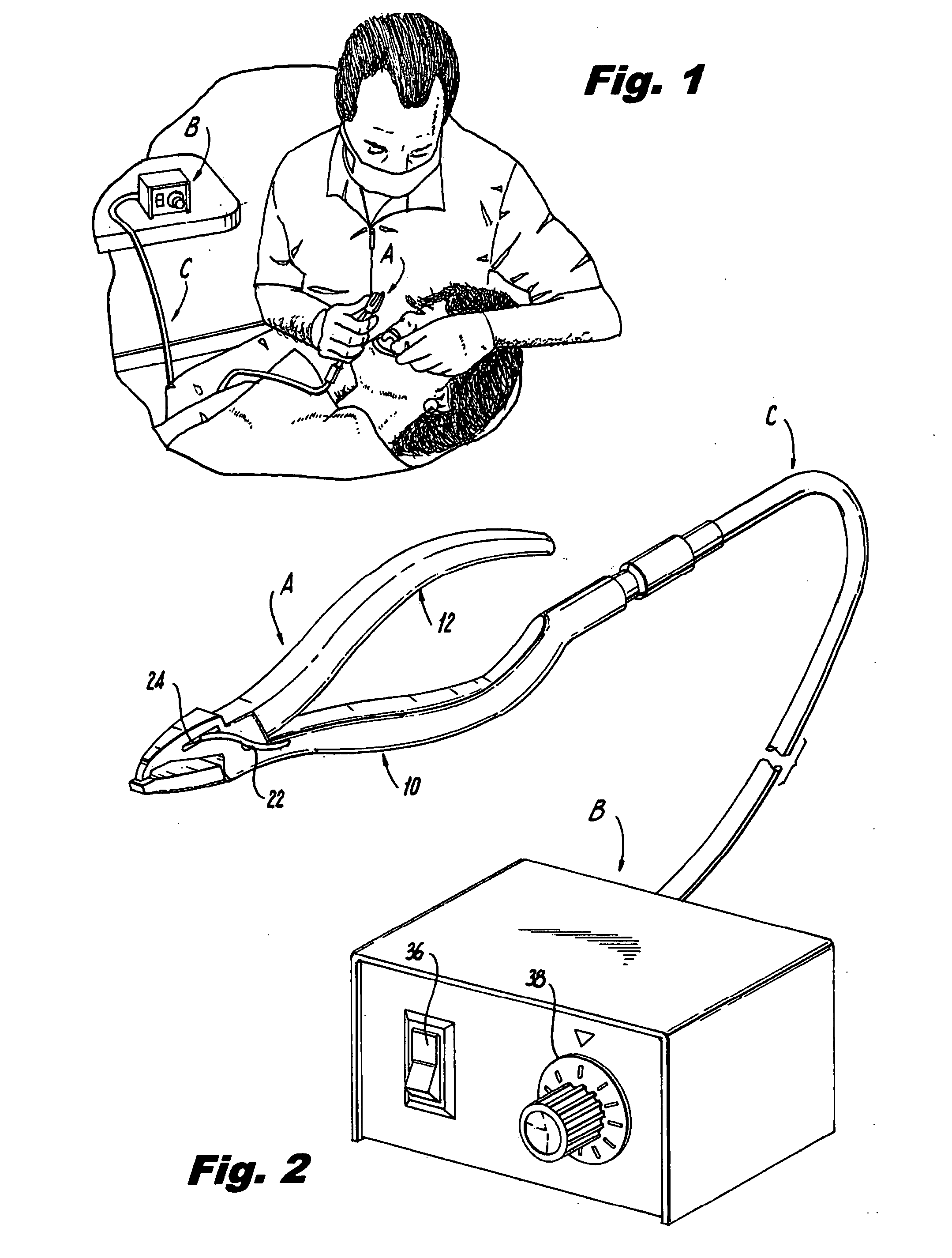
[0029]As seen in FIG. 2, the present invention includes electrically heated pliers, generally designated A, and a variable power source, generally designated B, connected to pliers A by an insulated cable, generally designated C. FIG. 1 illustrates how the invention would be used by a dentist to perform a procedure on a patient.

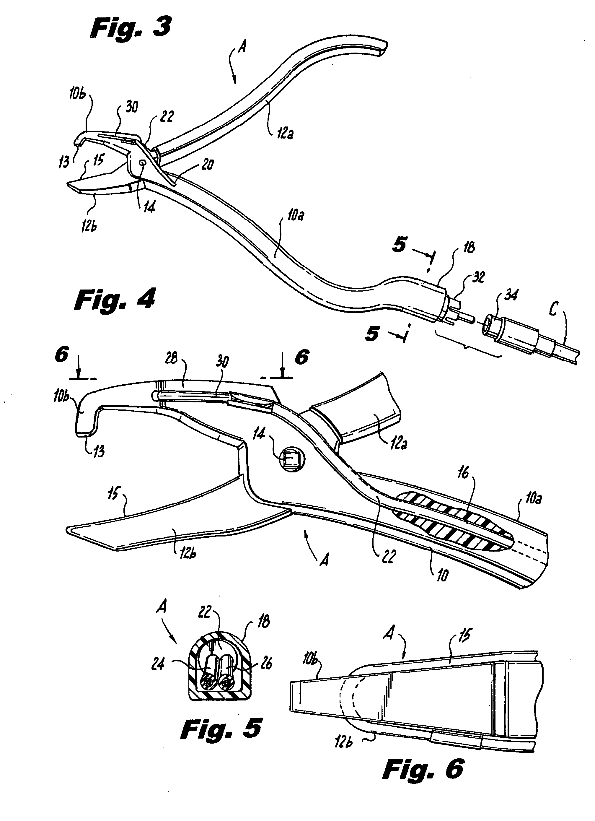
[0030]Pliers A, as shown in FIGS. 3 and 4, include first and second members 10, 12 made of heat conductive metal material, such as steel. Members 10 and 12 are connected for relative movement by a pin or shaft 14, as is conventional.

[0031]Each of the members 10, 12 consists of a handle portion 10a, 12a and a jaw portion 10b, 12b. The members pivot about shaft 14 such that the jaw portions 10b, 12b move between a proximate position, shown in FIG. 2, and a remote position, shown in FIGS. 3 and 4. The shapes of the individual jaw portions 10b, 12b of the pliers may differ in accordance with the particular application for which the tool is designed. In the prefer...


PUM


Abstract

The pliers, preferably in the form of dental pliers, include first and second members. Each of the members includes a handle portion and a jaw portion. The members are pivotally connected for movement of the jaw portions between remote and proximate positions. One of the jaw portions has a recess within which a nichrome heating element is situated. First and second wires extend into the recess and are connected to the heating element. The wires are connected to a variable power source to electrically energize the heating element such that the jaw portion of the pliers with the heating element is heated to the desired degree.

Description

CROSS-REFERENCE TO RELATED APPLICATIONS[0001]Not ApplicableSTATEMENT REGARDING FEDERALLY SPONSORED RESEARCH OR DEVELOPMENT[0002]Not ApplicableREFERENCE TO A “SEQUENCE LISTING”, A TABLE, OR A COMPUTER PROGRAM LISTING APPENDIX SUBMITTED ON COMPACT DISC[0003]Not ApplicableBACKGROUND OF THE INVENTION[0004]1. Field of the Invention[0005]The present invention relates to a tool, particularly but not exclusively to pliers used for dental procedures, which include an electrically heated jaw portion.[0006]2. Description of Prior Art Including Information Disclosed Under 37 CFR 1.97 and 1.98[0007]Pliers of various configurations are known in the art for use in a wide variety of different applications, including a variety of dental procedures. Some dental procedures require the application of heat at the same time as force is applied by the pliers.[0008]Certainly it is possible to heat one or more of the jaw portions of the metal pliers members using a flame or other external heat source. Howev...

Claims


Application Information

Patent Timeline
Patent Type & Authority Applications(United States)
IPC IPC(8): B25B7/02
CPCA61C3/10B25B7/02A61C7/04
Inventor NEVIN, DONALD
Owner NEVIN DONALD
Why Eureka
Try Eureka