Dental forceps structure

a technology of forceps and teeth, applied in the field of dental forceps structure, can solve the problems of shedding or poor fit, overtreatment has trouble situations, affecting the accuracy of filling combination, etc., and achieves the effects of convenient operation, effective fixation of water suction elements, and simple structur

Inactive Publication Date: 2021-03-11
LIU CHAO LIN
View PDF0 Cites 0 Cited by
  • Summary
  • Abstract
  • Description
  • Claims
  • Application Information

AI Technical Summary

Benefits of technology

[0007]To overcome the above shortcomings and to develop a dental forceps structure, which is structurally simple and conveniently operative, can fix a water suction element effectively, accurately prevent the disturbance of a tongue from interfering therapy, provide a physician's clear operational vision, and have advantages such as patient protection and medical accident prevention, the present invention is proposed.

Problems solved by technology

The above treatment has some trouble situations.
One of the trouble situations is that the patient's tongue may involuntarily disturb to push the gauze or lap out of the lingual side, or the contraction of the cheek muscles will push the gauze or lap out of the buccal side, causing the insolated area to be destroyed to cause saliva to contaminate the treatment area such that the dentist must isolate the affect part again, which wastes time or influences the accuracy of the combination of the filling material with the tooth, causing the shedding or poor fit thereof.
Another common trouble situation is that patients who are prone to laryngeal vomiting and reflexes are common in young children and some adults; such kinds of patients always cannot be inserted with gauze of lap into the lingual side when the composite resin is filled in the cavity or gap because it is easy to induce vomiting and reflex in the throat, causing gauze or lap to fall into the patient's esophagus or trachea, causing serious medical accidents and medical disputes.
Therefore, the affected parts cannot be surely isolated and dried, and therapeutic effects are reduced when the cavity filling with composite resin or gap for such kinds of patients is carried out.
However, the above treatment cannot be routinely used due to complicated operations, time consuming, and high material cost and because it is easy to accidentally hurt the gums when the rubber dam is clamped on the teeth, causing pain and bleeding.

Method used


Image

  • Dental forceps structure
  • Dental forceps structure
  • Dental forceps structure

Examples


Embodiment Construction

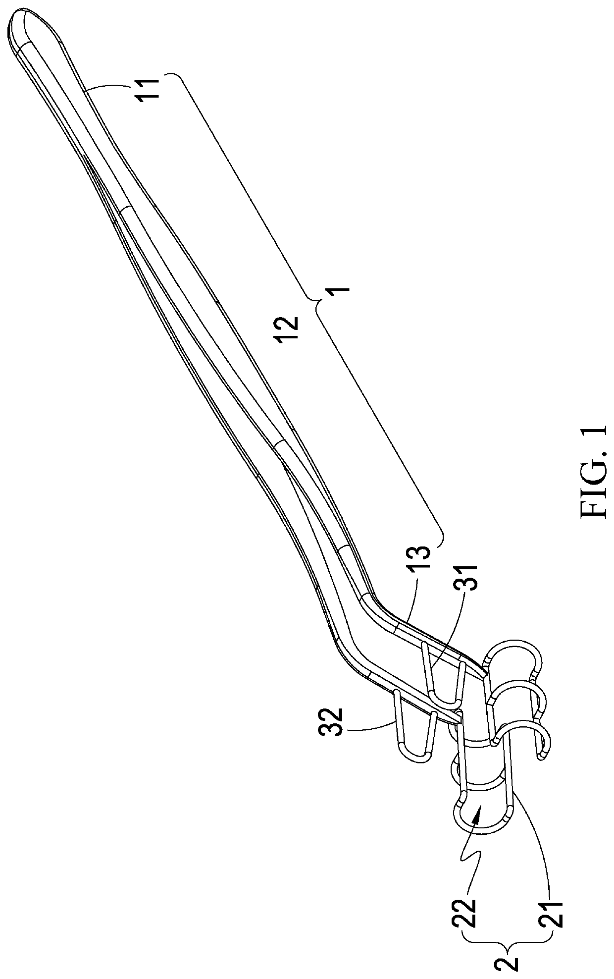
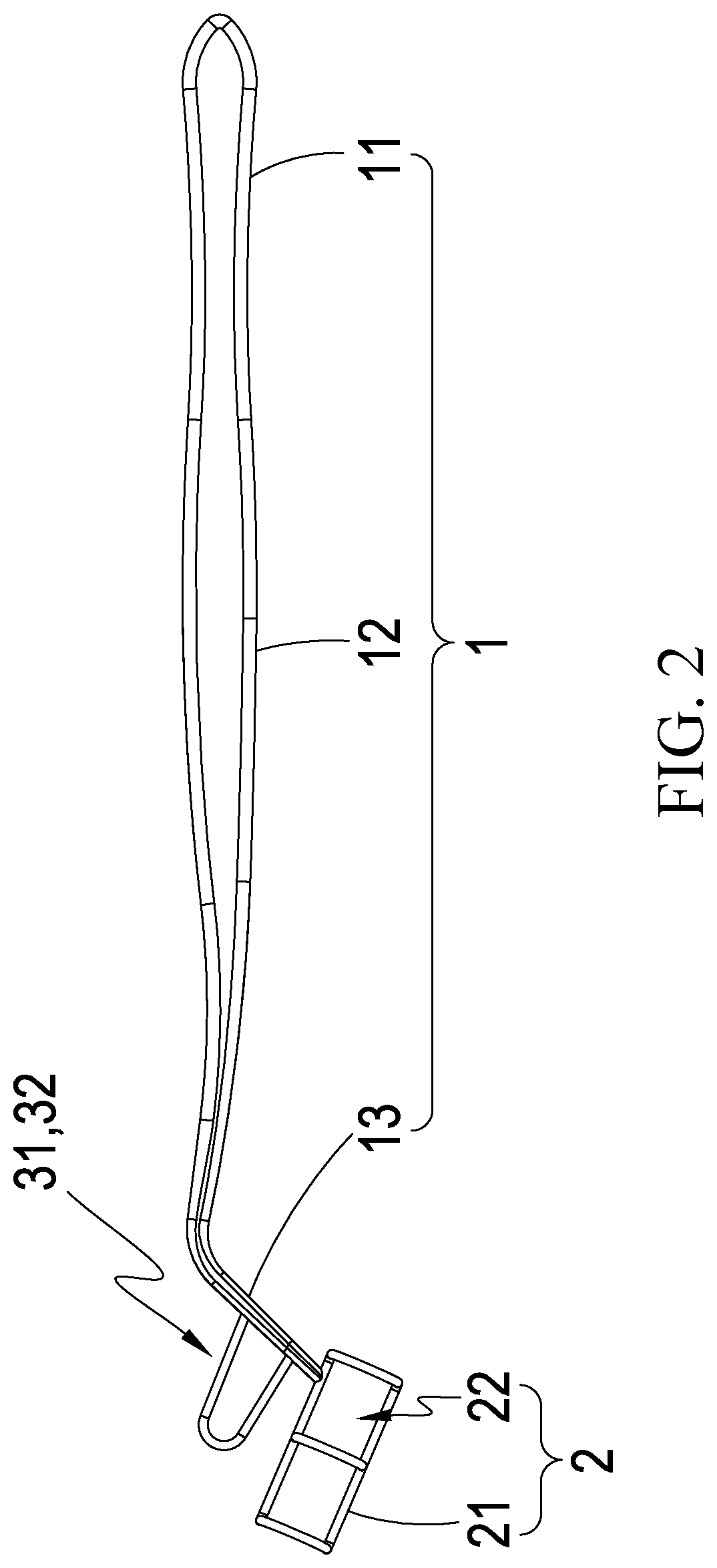
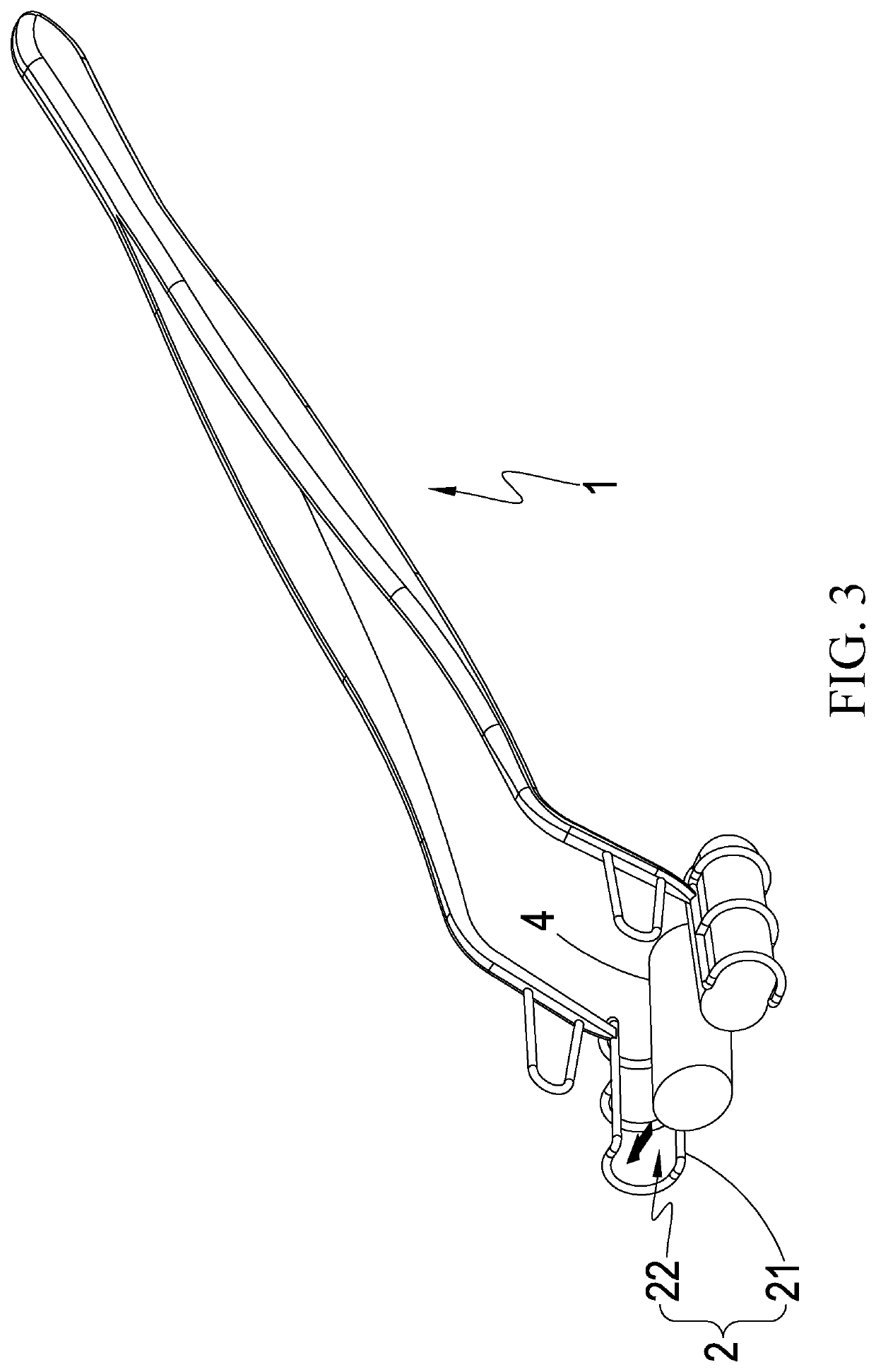
[0020]Referring to FIGS. 1 and 2, a dental forceps structure of the present invention, in a preferred embodiment, includes a fixture body 1, two accommodation elements 2 and two barriers 31, 32.

[0021]The fixture body 1 includes an elastic connecting portion 11, two elastic arms 12 formed on the two ends of the elastic connecting portion 11 and two bended clamping portions 13 each formed on one end of one of the elastic arms 12.

[0022]The two accommodation elements 2 are configured on the respective clamping portions 13, each of them has a countervailing limit 21, and at least one hollow portion 22 is defined between the two countervailing limits 21.

[0023]The two barriers 31, 32 are configured on the two respective clamping portions 13 and positioned between the accommodation elements 2 and fixture body 1; they are adapted to isolate the disturbance of surrounding tissues and organs.

[0024]With the above description, the structure of the present invention can be well understood. Accord...


PUM


Abstract

A dental forceps structure, including: a fixture body, including an elastic connection portion, two elastic arms formed on two ends of the elastic connection portion, and two bended clamping portions each formed on one end of one of the elastic arms; two accommodation elements, each configured on one of the clamping portions; and two barriers, configured on the respective clamping portions and positioned between the accommodation elements and fixture body, and adapted to isolate the disturbance of surrounding tissues and organs. With the above structure, a user only needs to manually pull the elastic arms apart after placing a water suction element between the accommodation elements and place the clamping portions on the two sides of an affected part, thereby using the elastic force of the elastic connection to contract the elastic arms inward to allow the clamping portions to be naturally fixed on the affected part.

Description

(a) TECHNICAL FIELD OF THE INVENTION[0001]The present invention relates to a dental forceps structure, and more particularly to a dental forceps structure, having a simple structure and convenient operation, capable of effectively fixing the position of a water suction element, preventing tongue disturbance from interfering therapy, further improving the therapeutic efficiency of physicians, providing a clear vision of the physician, and protecting patients from medical accident.(b) DESCRIPTION OF THE PRIOR ART[0002]Generally, dental physicians may use various different handheld devices to carry out oral examination or treatment of dental diseases for patients; the common handheld devices are high-speed handheld unit, forceps, mouth mirrors, probes, washing machines, etc., and general dental treatments includes dental filling, filling of the gap, root canal treatment, periodontal treatment, tooth extraction, etc. In the implementation of the preparation of a decayed tooth cavity and...

Claims


Application Information

Patent Timeline
Patent Type & Authority Applications(United States)
IPC IPC(8): A61C3/14A61C7/04
CPCA61C3/14A61C3/16A61C7/04A61C3/00A61C3/10
Inventor LIU, CHAO-LIN
Owner LIU CHAO LIN
Why Eureka
Try Eureka