
Double-sided grinding device with waste collecting structure for dental forceps processing

A technology of collecting device and tweezers, applied in the field of double-sided grinding devices, can solve the problems of low work efficiency, difficulty in cleaning where debris falls, affecting service life, etc., and achieve the effect of easy clamping

Inactive Publication Date: 2020-11-27
DONGGUAN RONGGONG AUTOMATION TECH CO LTD
View PDF0 Cites 0 Cited by
  • Summary
  • Abstract
  • Description
  • Claims
  • Application Information

AI Technical Summary

Problems solved by technology

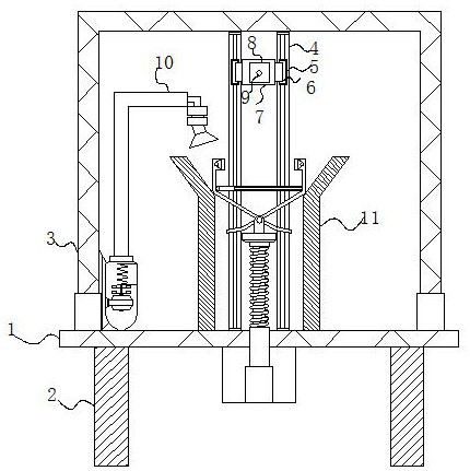
[0003] The existing double-sided grinding device drives the grinding disc through the rotating shaft on the motor to grind off the part to be removed. Due to the high-speed rotation of the motor, the polished debris is thrown out at high speed and then falls around the grinding table. Because the debris is very small and large in number, it is very difficult to clean the place where the debris falls. The double-sided grinding device itself has many movable parts, and these debris will adhere to the movable parts, which not only pollutes The working environment will also increase the wear of the grinding machine during long-term use, seriously affecting the service life, and when the clamping device clamps the workpiece, the clamping surface cannot be ground off, and the position of the workpiece is often adjusted manually , resulting in low work efficiency, therefore, we provide a double-sided grinding device with a waste collection structure for dental forceps processing

Method used


Image

  • Double-sided grinding device with waste collecting structure for dental forceps processing
  • Double-sided grinding device with waste collecting structure for dental forceps processing
  • Double-sided grinding device with waste collecting structure for dental forceps processing

Examples


Embodiment Construction

[0026] The following will clearly and completely describe the technical solutions in the embodiments of the present invention with reference to the accompanying drawings in the embodiments of the present invention. Obviously, the described embodiments are only some, not all, embodiments of the present invention.

[0027] In the description of the present invention, unless otherwise stated, the meaning of "plurality" is two or more; the terms "upper", "lower", "left", "right", "inner", "outer" , "front end", "rear end", "head", "tail", etc. indicate the orientation or positional relationship based on the orientation or positional relationship shown in the drawings, and are only for the convenience of describing the present invention and simplifying the description, rather than Indicates or implies that the device or element referred to must have a particular orientation, be constructed and operate in a particular orientation, and therefore should not be construed as limiting the...


PUM


Abstract

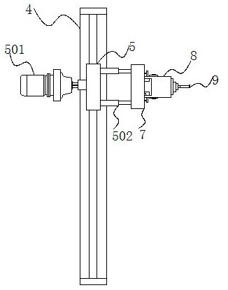
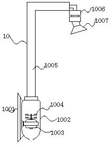
The invention discloses a double-sided grinding device with a waste collecting structure for dental forceps processing. The double-sided grinding device specifically comprises a bottom plate, whereinsupporting columns are fixed at the bottom of the bottom plate, a sliding rail is vertically arranged in the middle of the rear part of the inner side of a rack, a driving motor is arranged on the rear side of a sliding block, a telescopic rod is arranged on the front side of a connecting plate, a rotating motor is arranged on the front side of a mounting plate, and a collecting device is arrangedon the right side of a grinding head. According to the double-sided grinding device with the waste collecting structure for dental forceps processing, the sliding rail and the sliding block are arranged, so that components such as the grinding head can be driven to move on the sliding rail; meanwhile, the telescopic rod is arranged, so that the grinding head can move conveniently to be close to aworkpiece so as to grind the workpiece; a lifting rod is arranged, so that a clamping arm, a linkage rod and a clamping block can be driven to clamp the workpiece; and a rubber plate is adhered to the interior of the clamping block, so that the workpiece can be protected, and the workpiece can be prevented from sliding in the clamping block.

Description

technical field [0001] The invention relates to the technical field of mechanical grinding, in particular to a double-sided grinding device with a waste collection structure for dental tweezers. Background technique [0002] Double-sided grinding devices are widely used in finishing and surface polishing in the mold industry. With the development of technology, product processing equipment is also developing at a high speed. The quality of finished products is closely related to the effect of processing. [0003] The existing double-sided grinding device drives the grinding disc through the rotating shaft on the motor to grind off the part to be removed. Due to the high-speed rotation of the motor, the polished debris is thrown out at high speed and then falls around the grinding table. Because the debris is very small and large in number, it is very difficult to clean the place where the debris falls. The double-sided grinding device itself has many movable parts, and these...

Claims


Application Information

Patent Timeline
IPC IPC(8): B24B19/00B24B27/00B24B55/06B24B41/04B24B41/06B24B41/02B24B47/12B24B47/22
CPCB24B19/00B24B27/0076B24B41/02B24B41/04B24B41/06B24B47/12B24B47/22B24B55/06
Inventor 汪翠容邬仕伟王星亮
Owner DONGGUAN RONGGONG AUTOMATION TECH CO LTD
Learn More