Pressure Fluid Reservoir, Reservoir Unit, and Method For Producing a Pressure Fluid Reservoir

a technology of pressure fluid reservoir and reservoir unit, which is applied in the direction of braking system, braking components, transportation and packaging, etc., can solve the problems of limiting the installation space available for the restoring element in the reservoir housing, and limiting the freedom in terms of structural design of the reservoir piston further

Inactive Publication Date: 2008-08-14
ROBERT BOSCH GMBH
View PDF5 Cites 4 Cited by
  • Summary
  • Abstract
  • Description
  • Claims
  • Application Information

AI Technical Summary

Problems solved by technology

This limits the installation space available for the restoring element in the reservoir housing.
This limits the freedom in terms of structural design of the reservoir piston still further.

Method used


Image

  • Pressure Fluid Reservoir, Reservoir Unit, and Method For Producing a Pressure Fluid Reservoir
  • Pressure Fluid Reservoir, Reservoir Unit, and Method For Producing a Pressure Fluid Reservoir

Examples


Embodiment Construction

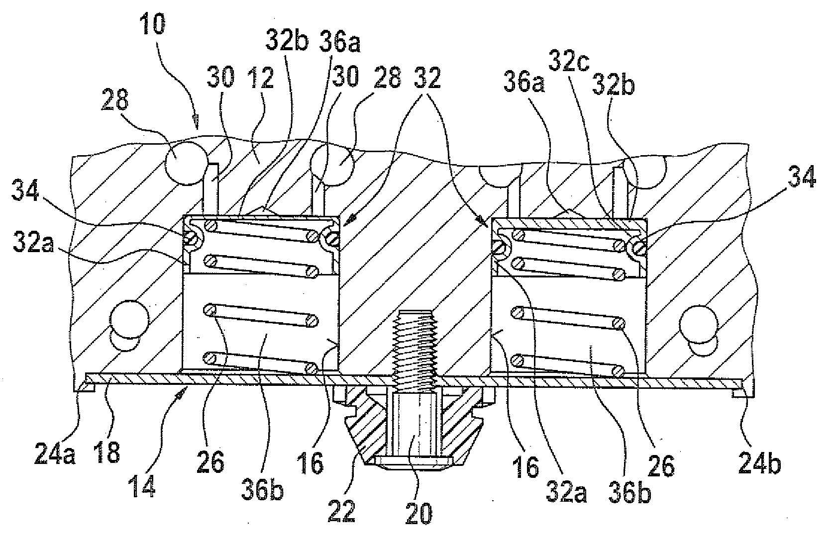
[0013]FIG. 1 shows a detail of a housing 10 of a hydraulic unit of a traction-controlled vehicle brake system. The housing 10 is formed by a metal block 12, in which installation spaces are provided for magnet valves, pumps, a pump drive, and pressure fluid reservoirs 14, among other elements. In FIG. 1, only the pressure fluid reservoirs 14 are shown, because the other components are of no significance for comprehension of the invention. Since for safety reasons vehicle brake systems typically have at least two circuits, a reservoir unit comprising a total of two pressure fluid reservoirs 14 is shown in FIG. 1. The function of the pressure fluid reservoirs 14 within a traction-controlled vehicle brake system has already been explained at the outset.

[0014]The reservoir housings 16 of the pressure fluid reservoirs 14 are formed by two separate blind bores. These bores originate at a common circumferential surface of the metal block 12 and have longitudinal axes that for example exten...


PUM


Abstract

A pressure fluid reservoir for a traction-controlled vehicle brake system; a reservoir unit including a plurality of pressure fluid reservoirs; and a method for producing a pressure fluid reservoir are disclosed. The pressure fluid reservoir with its structural size unchanged, has a larger installation space for a restoring element cooperating with a reservoir piston and at the same time can be produced economically. To that end, as the reservoir piston, a component reshaped in non-metal-cutting fashion from a sheet-metal material is proposed, on whose circumference an encompassing receptacle for a piston seal is integrally formed, likewise in non-metal-cutting fashion. The reservoir piston can be produced by deep drawing; the receptacle for the piston seal can be produced by roller-burnishing. Both method steps can be performed economically in one combined operation.

Description

PRIOR ART[0001]The invention is based on a pressure fluid reservoir as defined by the generic characteristics of the preamble to claim 1, a reservoir unit comprising a plurality of pressure fluid reservoirs as generically defined by the characteristics of the preamble to claim 9, and a method for producing a pressure fluid reservoir as generically defined by the characteristics of the preamble to claim 10.[0002]Pressure fluid reservoirs are used in hydraulic circuits of traction-controlled vehicle brake systems, for instance. Their task is to receive pressure fluid from one of the wheel brakes, so that when needed a rapid reduction in the brake pressure in this wheel brake is made possible. Besides a hydraulic communication with a wheel brake, the pressure fluid reservoir has a hydraulic communication with the intake side of an electrically drivable pressure generator of the vehicle brake system. This pressure generator evacuates the pressure fluid reservoir depending on the operati...

Claims


Application Information

Patent Timeline
Patent Type & Authority Applications(United States)
IPC IPC(8): B60T17/06
CPCB60T8/368B60T8/4275F15B2201/61F15B2201/21F15B2201/312F15B1/04
Inventor WEH, ANDREASBAREISS, ALEXANDERMCCORMICK, NATHANFISCHER, HOLGER
Owner ROBERT BOSCH GMBH
Why Eureka
Try Eureka