Blower housing and method of manufacture

a technology of blower housing and manufacturing method, which is applied in the direction of manufacturing tools, machines/engines, liquid fuel engines, etc., can solve the problems of significant operating and yield loss, movement and/or separation problems, and scrapping during the manufacturing or repair process, and achieve the effect of preventing slippage in seams or joints

Inactive Publication Date: 2008-08-14
HOEFFKEN RUSSELL W
View PDF6 Cites 21 Cited by
  • Summary
  • Abstract
  • Description
  • Claims
  • Application Information

AI Technical Summary

Benefits of technology

[0012]The art of the present invention comprises a new and improved blower housing utilizing a unique joint or seam for attaching both side walls to a wrapper wall sheet. The improved blower housing comprises a first side wall, a second side wall opposite the first side wall, and a wrapper wall sheet attached intermediate the first side wall and the second side wall. The present art prohibits slippage in the seams or joints between the side walls and wrapper wall which is especially useful during manufacturing with worn or out of adjustment forming machines. It further allows use of spring loaded forming rollers within the forming machine whereby a wide range of materials (including thicknesses) may be utilized.

Problems solved by technology

This movement and / or separation problem is particularly apparent during final assembly of the complete blower unit.
(i.e. motor and blower fan installation) When separated, the side walls and the wrapper wall sheet are no longer usable thereby causing significant operating and yield loss (e.g. scrap) during the manufacturing or repair process.
Prior art blower housings attempt to address the blower housing separation problem by utilizing either spot welds and / or auxiliary fasteners, such as end screws, neither of which is satisfactory since both increase the manufacturing cost of the blower housing.

Method used


Image

  • Blower housing and method of manufacture
  • Blower housing and method of manufacture
  • Blower housing and method of manufacture

Examples


Embodiment Construction

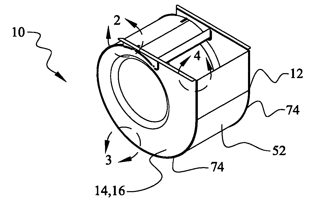
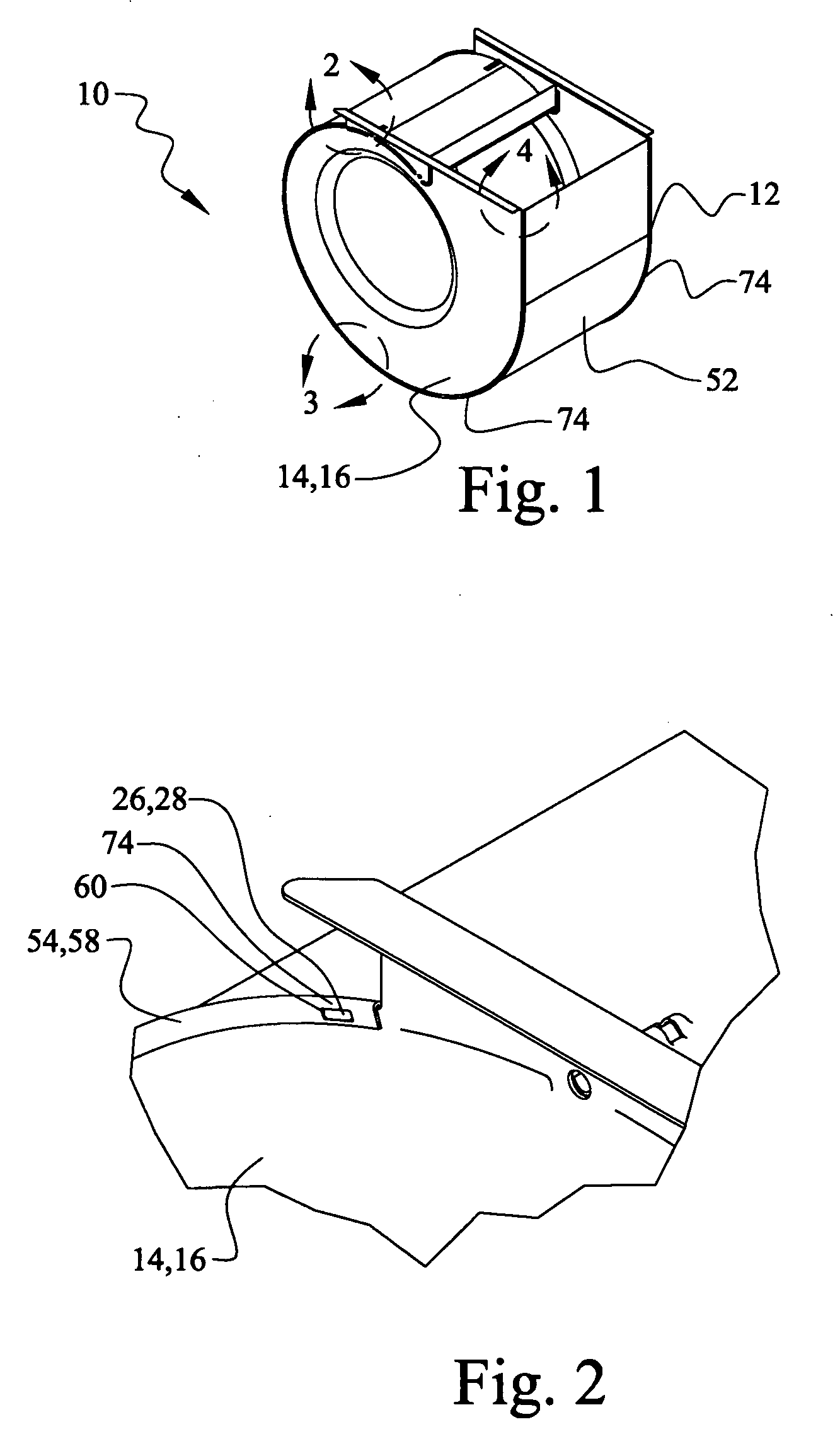
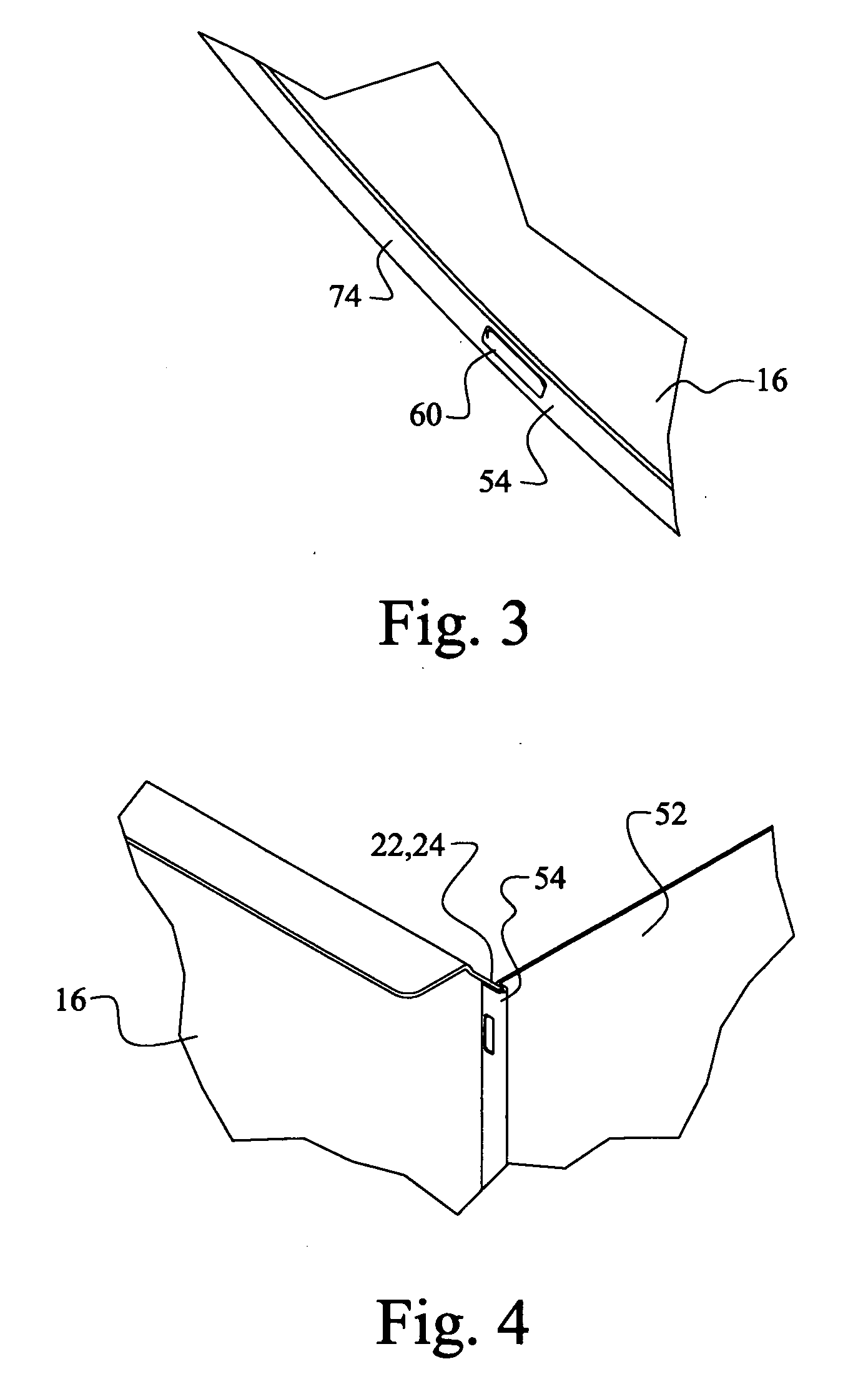
[0040]Referring now to the drawings, there is shown in FIGS. 1-10a a preferred embodiment and in FIGS. 11-13a alternate embodiments of the improved blower housing and method of manufacture 10. The improved blower housing 10, 12 comprises a first side wall 16, a second side wall 32 (collectively sidewalls 14) opposite the first side wall 16, and a wrapper wall sheet 52 attached intermediate the first side wall 16 and the second side wall 32.

[0041]In a preferred embodiment, the wrapper wall sheet 52 has a first lateral edge flange 54 and a second lateral end flange 64 opposite the first lateral edge flange 54. The first lateral edge flange 54 comprises a first inner portion 56 and a first outer portion 58 having one or more first apertures 60 and the opposite second lateral edge flange 64 comprises a second inner portion 66 and a second outer portion 68 having one or more second apertures 70. The first side wall 16 has a first inner surface 18, a first outer surface 20, and a first ci...


PUM

PropertyMeasurementUnit
angleaaaaaaaaaa
angleaaaaaaaaaa
thicknessesaaaaaaaaaa

Abstract

An improved blower housing and method of manufacture comprising a wrapper wall sheet conjoined with a first side wall and a second side wall and held together with a seam interlocked with mating protrusions and apertures. The housing design may utilize different types and thicknesses of conjoined materials and reuse the components when separated. Unlike prior art blower housing seams, the present art provides a substantially smooth positive locking seam without the use of welds or fasteners.

Description

[0001]This application claims priority of U.S. Provisional Patent Application No. 60 / 627,805, filed Nov. 15, 2004.BACKGROUND OF THE INVENTION[0002]The art of the present invention relates to blower housings for blower fan assemblies used in HVAC systems although the present invention can also be utilized in other industries employing blower systems. The improved blower housing of the present invention incorporates a uniquely formed joint or seam having a combination locking tab and slot which provides positive lockup of the blower housing side walls to a blower housing wrapper wall sheet. The present art essentially eliminates unintentional separation of the formed unit both prior to final manufacturing assembly and during its entire useful service life.[0003]Blower housings of the type pertaining to the present invention are typically employed in forced air heating furnaces or air conditioners. In most cases, the blower is assembled in the interior of the HVAC equipment. Ambient ai...

Claims


Application Information

Patent Timeline
Patent Type & Authority Applications(United States)
IPC IPC(8): F04D29/42F04D29/40B23P11/00
CPCB23P15/00F04D29/4226F04D29/626Y10T29/49915Y10T29/49936Y10T29/49243Y10T29/49922
Inventor HOEFFKEN, RUSSELL W.
Owner HOEFFKEN RUSSELL W
Why Eureka
Try Eureka