Flashlight with rotatable handle

a spotlight and rotatable technology, applied in the direction of electric lighting with batteries, lighting support devices, lighting and heating apparatus, etc., can solve the problems of limited utility of prior art spotlights, inconvenient placement on a planar support surface for directing beams, and inability to self-support, so as to avoid prolixity and facilitate understanding

Inactive Publication Date: 2008-08-21
BLACK & DECKER INC
View PDF11 Cites 45 Cited by
  • Summary
  • Abstract
  • Description
  • Claims
  • Application Information

AI Technical Summary

Benefits of technology

[0012]Further areas of applicability of the various exemplary embodiments of the portable light described herein will become apparent from the detailed description provided hereinafter. It should be understood that the detailed description and specific examples, while indicating various exemplary embodiments of the flashlight, are intended for purposes of illustration only and are not intended to limit the scope of the invention. Further, the following description and accompanying drawings provide multiple features and embodiments that are usable together, but may be shown separately to avoid prolixity and facilitate ease of understanding.

Problems solved by technology

Flashlights of such a design have the disadvantage that they cannot conveniently be placed on a planar support surface for directing the beam in a desired direction.
The utility of these types of prior art spotlights is limited, however, in that they typically do not include a base with legs or a planar lower surface, and therefore are not self supporting.
That is to say, such lights cannot be placed on a support planar support surface.
Other prior art spotlights can be coupled with a tripod, such as that used for cameras or surveying equipment, but such tripods are bulky and inconvenient to use.
Planar supports for a portable spotlight or flashlight are frequently unavailable in such circumstances.
Most prior art flashlights lack a mechanism for easily suspending the light from an elevated support or beam where a planar support surface is unavailable.

Method used


Image

  • Flashlight with rotatable handle
  • Flashlight with rotatable handle
  • Flashlight with rotatable handle

Examples


Embodiment Construction

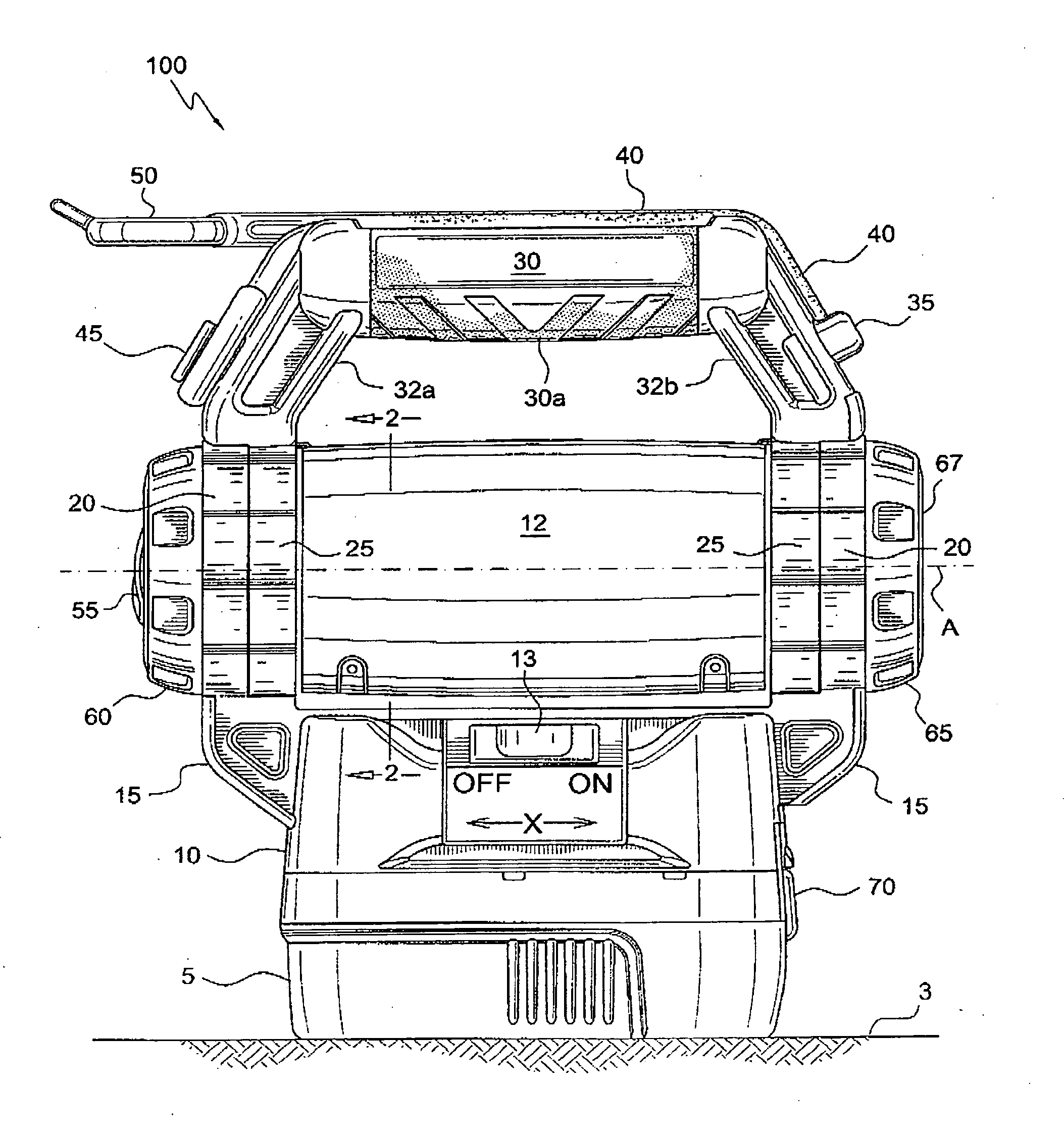
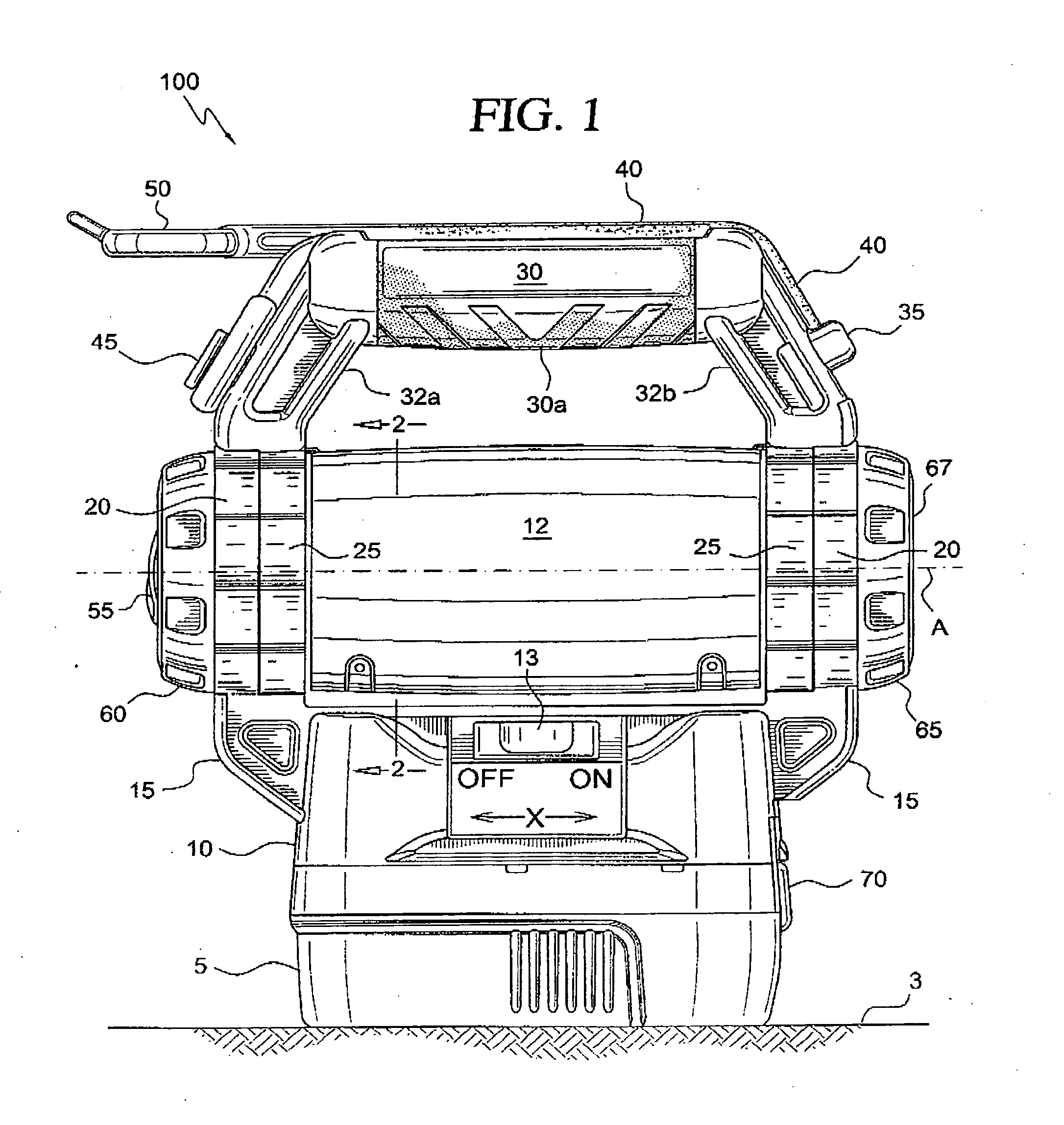
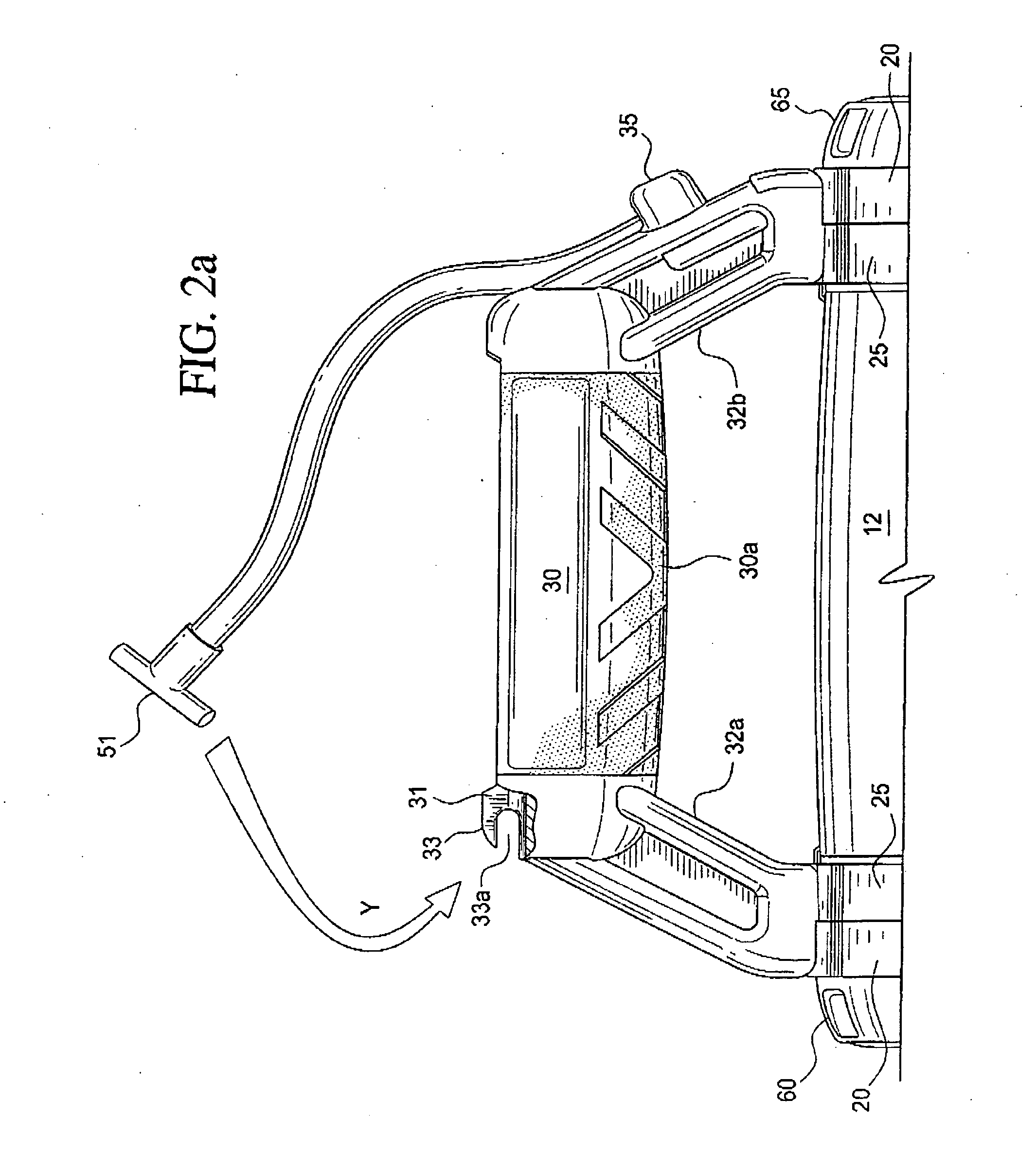
[0021]Referring now to the drawings, in which like numerals refer to like components or steps, there are disclosed broad aspects of various exemplary embodiments. FIG. 1 is a side view showing features of various exemplary embodiments of the flashlight disclosed herein. In various exemplary embodiments, flashlight 100 includes a rechargeable battery 5 which is releasably attached to base 10 of the flashlight 100, where base 10 has a substantially planar bottom surface. Battery 5 has a planar bottom surface which may be used to rest flashlight 100 on a planar surface 3. Tubular flashlight housing 12 is mounted on base 10 by at least one support 15. In various exemplary embodiments, supports 15 are each mounted to one of two rings 20. In various exemplary embodiments, a single support 15 may be directly mounted to housing 12. Rings 20 each surround one end of housing 12, and are non-rotatably mounted to housing 12 so as to hold housing 12 in an orientation such that an axis A of housi...


PUM


Abstract

A portable flashlight includes a housing having a first end, a second end, a base, and an axis running from the first end to the second end of the housing. A rechargeable battery is connected to the base of the housing, so that the battery may be used as a stand for the battery. In the first end of the flashlight, a parabolic reflector having a focus is positioned, so that the focus of the reflector is positioned on the axis of the housing. A fixture or socket for holding an electric light is positioned so as to hold the light at the focus of the reflector. A handle is connected to the housing, where the handle has a first end and a second end. An elastic cord runs from the first end of said handle to the second end of the handle; and one end of the elastic cord may be released from the handle, wrapped around a support for the flashlight, and reattached to the handle. The handle may be rotated relative to the axis of the housing.

Description

BACKGROUND[0001]1. Field[0002]The subject matter disclosed herein generally relates to flashlights or portable spotlights with rechargeable batteries. In various preferred embodiments, the flashlights or portable spotlights may be handheld, or may be releasably secured to a convenient support.[0003]2. Description of the Prior Art[0004]Flashlights and portable spotlights in the prior art frequently, include a tubular body with a light positioned at one end. The tubular body is sized so that it may be conveniently grasped by a user. Flashlights of such a design have the disadvantage that they cannot conveniently be placed on a planar support surface for directing the beam in a desired direction. This is because the tubular body is subject to rolling on the planar surface. Other flashlights and portable spotlights in the prior art include a handle for grasping by the user. The utility of these types of prior art spotlights is limited, however, in that they typically do not include a ba...

Claims


Application Information

Patent Timeline
Patent Type & Authority Applications(United States)
IPC IPC(8): F21L4/00F21V7/00
CPCF21L4/00F21V21/406F21V21/08
Inventor O'HERN, ADAM
Owner BLACK & DECKER INC
Why Eureka
Try Eureka