Babycare Heating Apparatus

Inactive Publication Date: 2008-08-21
KONINKLIJKE PHILIPS ELECTRONICS NV
View PDF7 Cites 15 Cited by
  • Summary
  • Abstract
  • Description
  • Claims
  • Application Information

AI Technical Summary

Problems solved by technology

A problem with this design of steriliser is that effective sterilisation is dependent on the user charging it with the correct amount of water.

Method used


Image

  • Babycare Heating Apparatus
  • Babycare Heating Apparatus
  • Babycare Heating Apparatus

Examples


Embodiment Construction

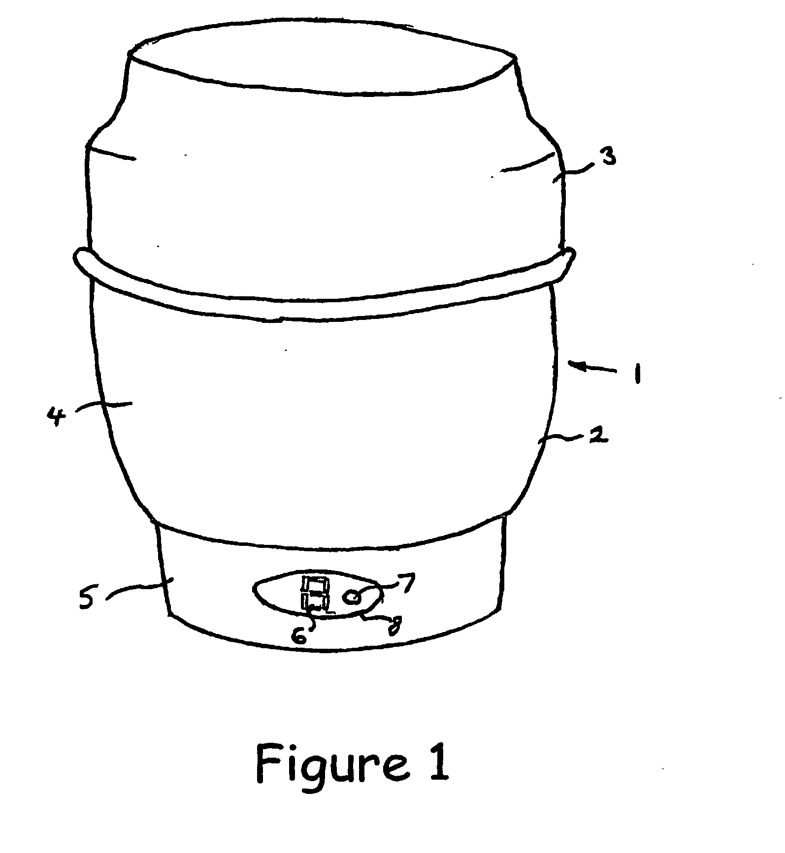
[0038]Referring to FIG. 1, a steriliser 1 comprises an opaque body 2 formed from polypropylene and a transparent plastic lid 3, also formed from polypropylene. The body 2 comprises an upper bowl part 4 over a pedestal part 5. Items to be sterilised are placed in the upper bowl put 4. The pedestal part 5 contains the steriliser's electrical components. A 7-segment led display 6 and a push button switch 7 are located in an elliptical aperture 8 in the side wall of the pedestal part 5.

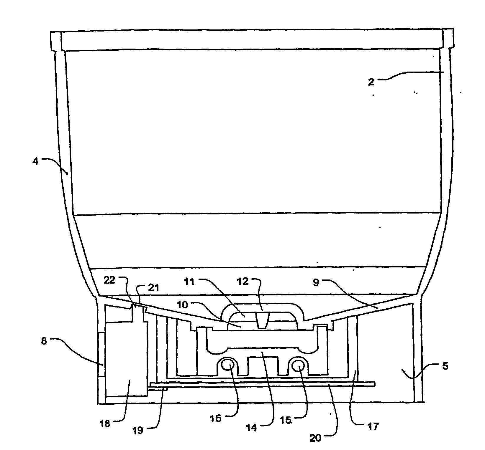
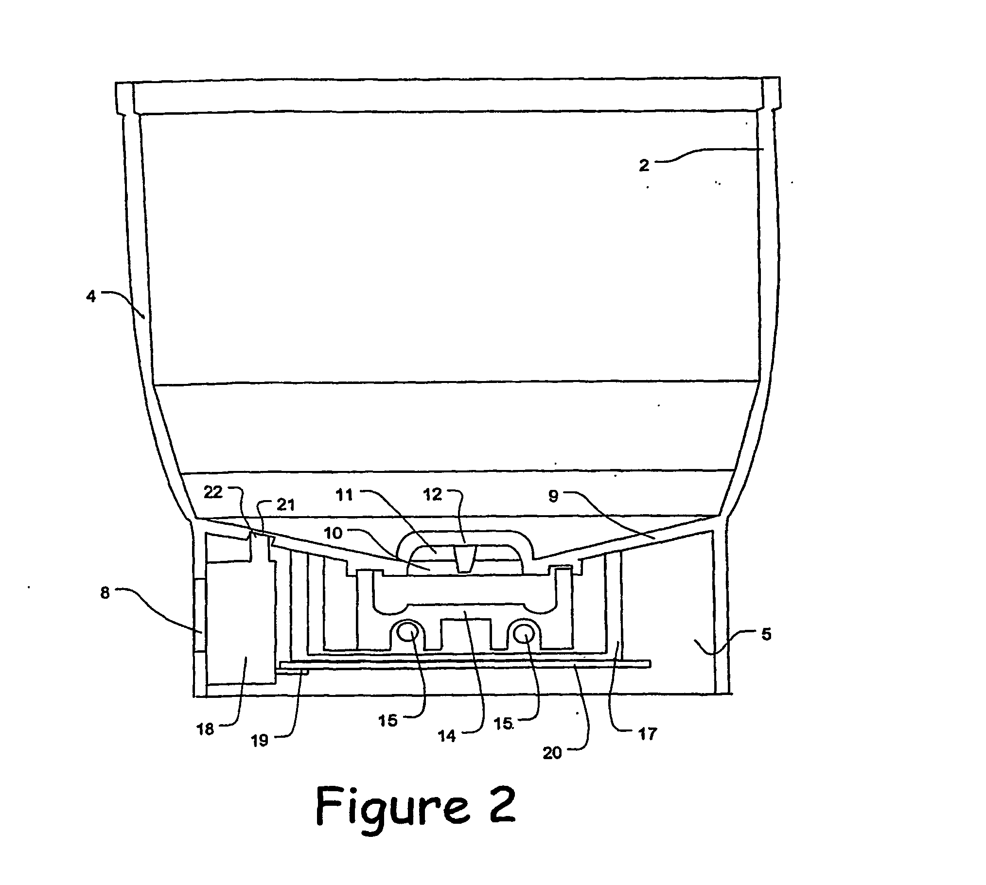
[0039]Referring to FIG. 2, which omits some structural details unnecessary for an understanding of the present invention, the floor 9 of the bowl part 4 is slightly dished and has a central roofed aperture 10. Gaps 11 between the roof 12, over the aperture 10, and the surrounding part of the floor 9 open into a small cast metal trough 14. A electric heating element 15, rated at 500 W at 110V, is mounted to the underside of the trough 14. The trough 14 and its heating element 15 are clamped in place by a c...


PUM

PropertyMeasurementUnit
thicknessaaaaaaaaaa
thicknessaaaaaaaaaa
thickaaaaaaaaaa

Abstract

A babycare heating apparatus comprising a vessel (2;102) for containing water and a heating element (15;115) for heating water held in the vessel, characterised by: a temperature sensor (22;42,123) for sensing a temperature rise effected by operation of the heating element (15); and control means (25;125) for controlling the energising of the heating element (15;115) in dependence on the output of the temperature sensor (22;42;123) and being configured to de-energise the heating element (15;115) if the change in the temperature, sensed by the sensor (22;42;123), meets a predetermined criterion. The apparatus can be used as a steriliser or a bottle warmer and its uses a measure of the rate of heating during operation to determine whether the apparatus has been correctly charged with water.

Description

FIELD OF THE INVENTION[0001]The present invention relates to babycare heating apparatus.BACKGROUND TO THE INVENTION[0002]Electric sterilisers for baby feeding bottles are well-known. Such sterilisers arm designed to subject the items being sterilised to a temperature of 80° to 100° for several minutes.[0003]In a known design, the operating period is set by loading the apparatus with a predetermined amount of water which evaporates during operation of a heating element. The temperature of the heating element is monitored using a bimetallic thermal switch and when the temperature of the heating element reaches a threshold temperature, indicating that all the water has evaporated or boiled off, the thermal switch opens to cut off the supply of power to the heating element.[0004]A problem with this design of steriliser is that effective sterilisation is dependent on the user charging it with the correct amount of water. Additionally, the effective operational time varies according to th...

Claims


Application Information

Patent Timeline
Patent Type & Authority Applications(United States)
IPC IPC(8): A47J36/24A61L2/24F24H1/06G05D23/00A61L2/04
CPCA47J36/2438A61L2/24A61L2/04
Inventor WORTLEY, MARK JOHN
Owner KONINKLIJKE PHILIPS ELECTRONICS NV
Why Eureka
Try Eureka