Dual chambered fluid dispenser with mixing chamber

a fluid dispenser and mixing chamber technology, applied in liquid transferring devices, flexible tubular containers, transportation and packaging, etc., can solve the problems of erratic fluid volume, valve opening, and more fluid material to be deposited

Active Publication Date: 2008-08-28
1TOUCH HLDG INC
View PDF99 Cites 16 Cited by
  • Summary
  • Abstract
  • Description
  • Claims
  • Application Information

AI Technical Summary

Benefits of technology

[0009]In this regard, the present invention preserves the advantages of prior art metering dispensing devices and dual reservoir fluid containers. In addition, the present invention provides new advantages not found in currently available devices and overcomes many disadvantages of such currently available devices.

Problems solved by technology

While this method has provided marginally acceptable results, this method also typically yields an erratic fluid volume since more or less fluid material may be delivered on each successive squeeze of the container body.
The difficulty here is that the valve over time becomes partially clogged thereby requiring that the user apply additional pressure to cause the valve to open.
As a result, once the valve opens, the additional pressure causes more fluid material to be deposited than the user typically would have desired.
While in the prior art, the concept of dual chambered product storage containers is not novel, the user typically had little control over the amount or rate at which the material in the two chambers was combined.
In other words, the previously available prior art devices are incapable of delivering a substantially equal dose of fluid with each operation because they simply open up the container body and permit the combination of the two fluids that were previously maintained separately in the two chambers.
In this context, such a lack of control is highly undesirable when a user is attempting to controllably mix products like hair colorants.
In view of the foregoing, there is need for a device that eliminates prior art dual chambered containers that suffer from various disadvantages detailed above that make them difficult and awkward to use.
Further, because these prior art dispensers often provide a user with unexpected results, there is a need for a dual reservoir fluid container that includes a selective metering mechanism that is easy to operate.

Method used


Image

  • Dual chambered fluid dispenser with mixing chamber
  • Dual chambered fluid dispenser with mixing chamber
  • Dual chambered fluid dispenser with mixing chamber

Examples


Embodiment Construction

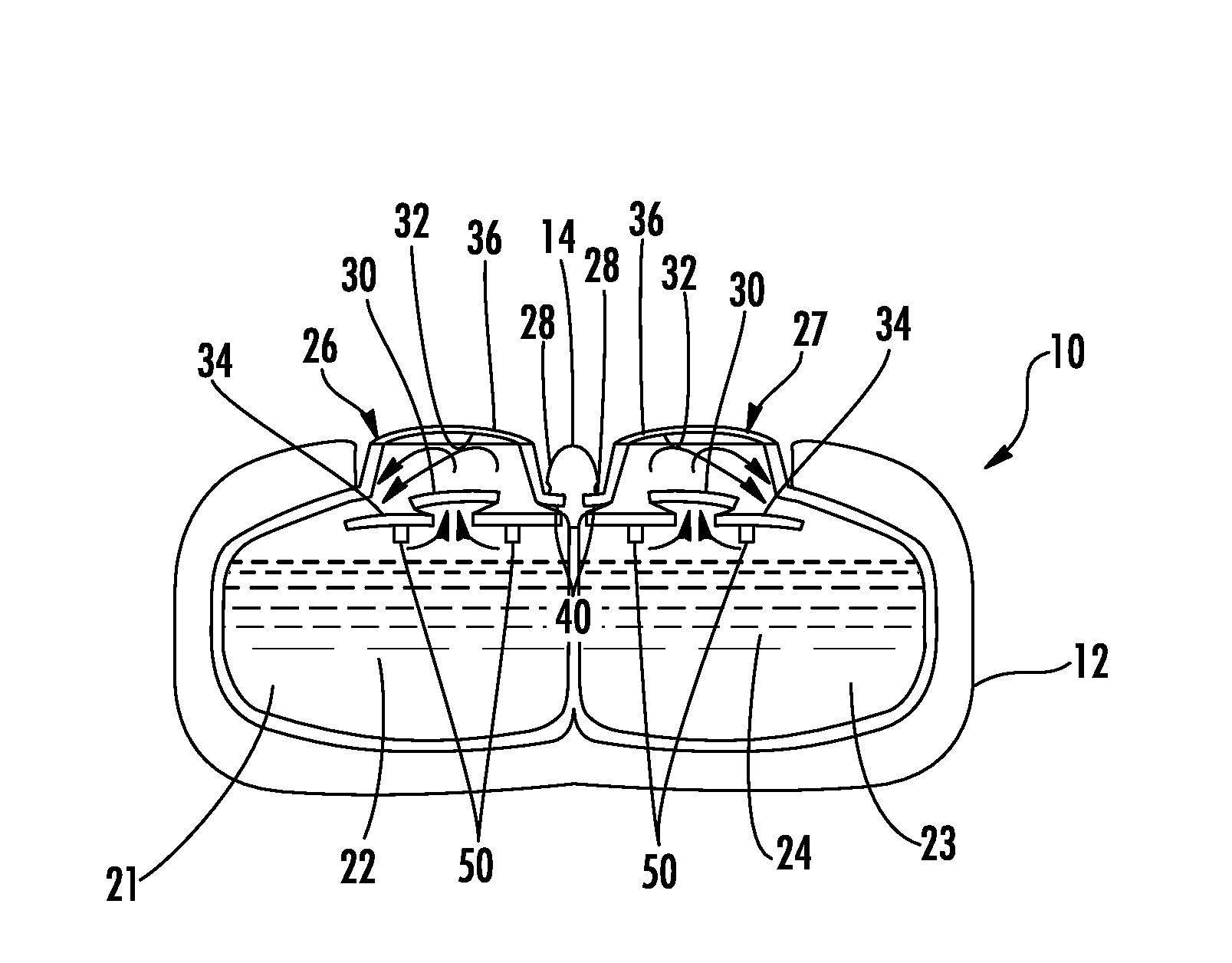
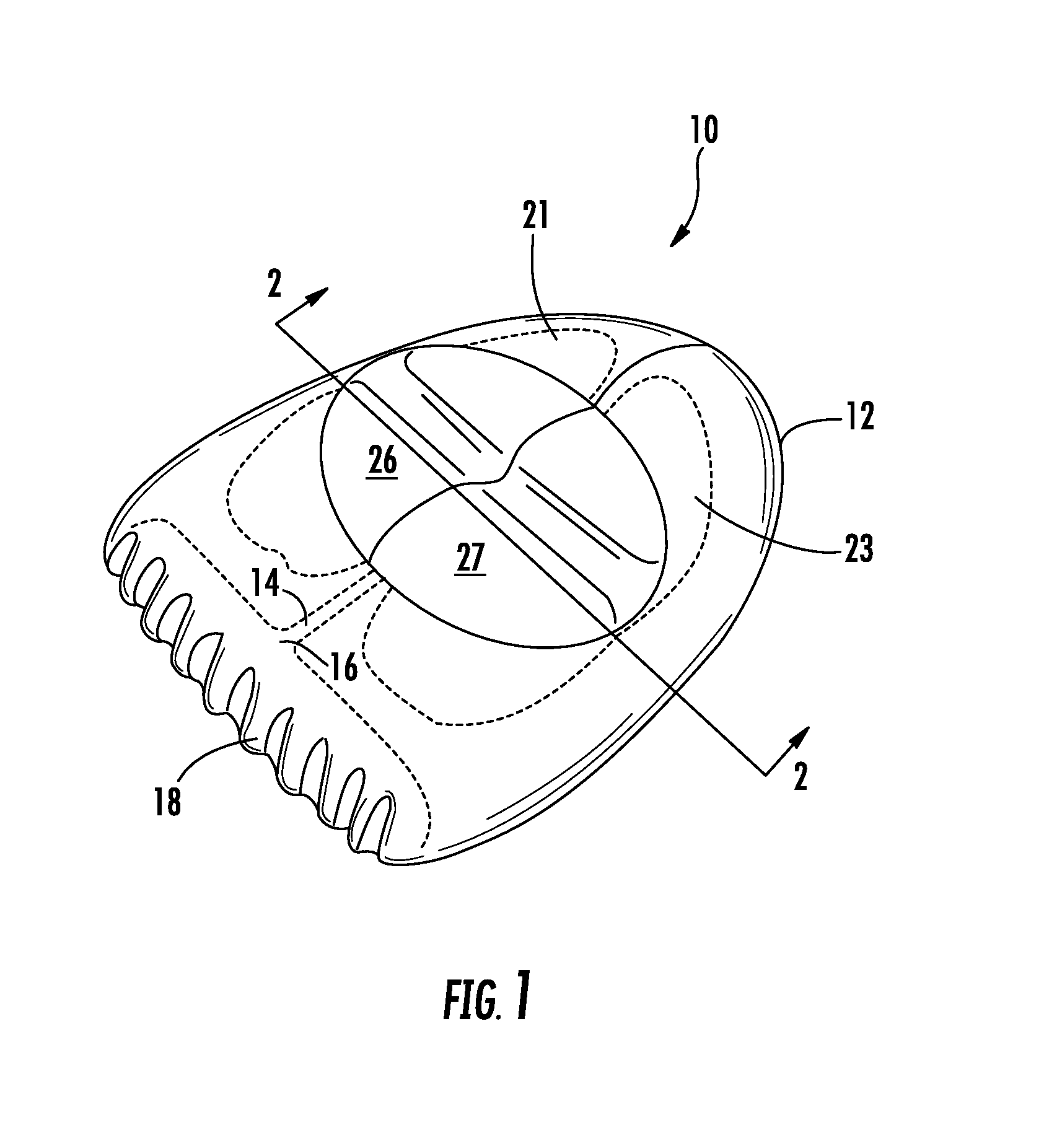
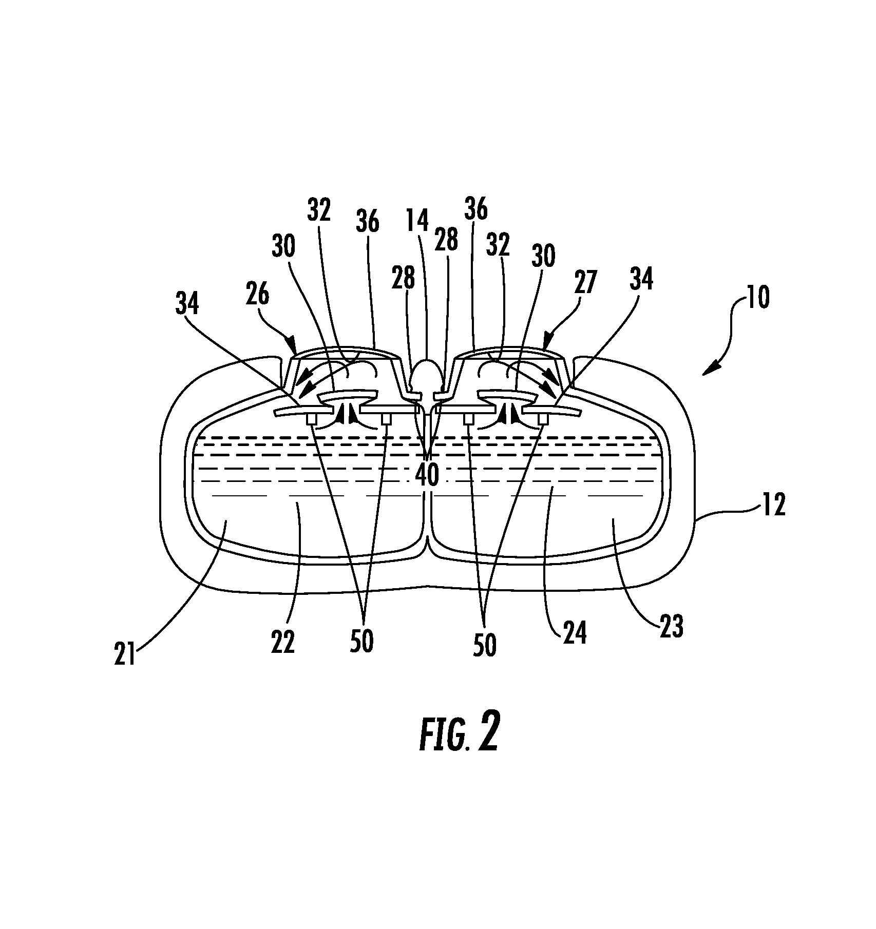
[0023]Now referring to the drawings, a first embodiment of the dispensing device of the present invention is shown and generally illustrated at 10 in FIG. 1. As can be seen, the dispensing device 10 of the present invention has a main body 12 that is generally shown to include a first fluid reservoir 21 containing a first fluid 22, a second fluid reservoir 23 containing a second fluid 24. A first metered dosing pump 26 is provided in fluid communication with the first fluid reservoir 21 and is operable to transfer a portion of the first fluid 22 from the first fluid reservoir 21 to a mixing chamber 14. A second metered dosing pump 27 is provided in fluid communication with the second fluid reservoir 23 and is also operable to transfer a portion of the second fluid 24 from the second fluid reservoir 23 to the mixing chamber 14. In the mixing chamber 14, the first and second fluids 22, 24 are mixed and then dispensed from an exit aperture 16 for delivery to the user. The device 10 may...


PUM


Abstract

A dispensing device is provided that includes at least two separate reservoirs therein and a dispenser for mixing and delivering a substantially equal metered dose of fluid material from the reservoirs with each dispensing operation. In one example, the present invention relates to a dispenser for mixing and delivering hair colorant that allows the user to dispense a metered dose of the hair colorant components in a manner that measures and mixes those components with each dispensing operation. An optional applicator may be provided for even distribution of the dispensed hair colorant material.

Description

CROSS-REFERENCE TO RELATED APPLICATIONS[0001]This application is related to and claims priority from earlier filed U.S. Provisional Patent Application No. 60 / 891,312 filed Feb. 23, 2007.BACKGROUND OF THE INVENTION[0002]The present invention relates generally to product packaging and / or containers that include integrated dispensing devices. More specifically, the present invention relates to a multiple reservoir fluid container that allows the user to introduce a metered amount of fluid from each of the reservoirs into a mixing chamber that serves to mix and apply the fluid material.[0003]Various types of fluid material and media are employed for different purposes throughout commerce and industry. For example, there are various products in the areas of personal care, home care, air care, transportation care and food industries that require a fluid material to be dispensed in some manner from a source of such material. Further, when this material is sold in commerce, it must be conta...

Claims


Application Information

Patent Timeline
Patent Type & Authority Applications(United States)
IPC IPC(8): B67D5/52B65D37/00B67D7/70
CPCB65D81/3261
Inventor LAFLAMME, ROGER J.WARNER, JIM F.
Owner 1TOUCH HLDG INC
Why Eureka
Try Eureka