Combination hand tool bar

a tool bar and combination technology, applied in the field of nail pulling devices, can solve the problems of insufficient leverage, difficult and slow removal of materials, and insufficient removal of materials, so as to improve the ergonomic function, minimize user discomfort, and increase the leverage during operation

Inactive Publication Date: 2008-09-11
VAUGHAN & BUSHNELL MANUFACTURING
View PDF11 Cites 22 Cited by
  • Summary
  • Abstract
  • Description
  • Claims
  • Application Information

AI Technical Summary

Benefits of technology

[0029]Another aspect of the present invention is to provide a combination hand tool bar that provides enhanced ergonomic function, minimizes user discomfort, and increased leverage during operation on both ends of a bar shank member.
[0030]The present invention relates to a combination hand tool bar device suitable for pulling nails and other materials from surfaces, with improved user ergonomics and efficient force transfer. The device includes a hook end and a pry end joined by a bar shank member interposed there between. The hook end further comprises a compound curve projecting in the same direction from the bar shank member as the pry end enabling an increased user throw and ergonomic comfort.
[0031]According to an embodiment of the present invention there is provided a combination hand tool bar, comprising: a bar shank member spacing a hook end portion at a proximate end and a curved pry end portion at a distal end thereof, the bar shank member defining a first plane having a front side and a back side, the hook end portion and the curved pry end portion extending from the bark shank portion on the same side thereof, whereby the hand tool bar provides increased lever throw and user comfort, and an angle defined between the of the hook end portion and the first plane being less than sixty (60) degrees, whereby the hand tool bar enables an increased leverage during a use.

Problems solved by technology

With respect to particularly difficult-to-remove items, and more particularly on difficult-to-access surfaces such as roofs or slanted walls, removal can be difficult since conventional prying tools tend to be generally straight or with very short (less than 90 degree) single-curve hooked pulling heads.
Such straight or hooked pulling heads do not provide sufficient leverage against the angled or awkwardly positioned surfaces, and pulling materials is difficult and slow, requiring repeated pulling to remove materials with a large surface area.
Additionally, when dealing with particularly large materials (such as roofing tiles), the short curved surface is generally too short in length to provide an efficient detachment of the materials.
Additionally, this conventional construction also limits the position of a user's hands when initially locating the hook end under the item to-be-lifted (e.g. the head of a nail).
In these cases, the nail pulling operation is inefficient since the upward motion of the material to be pulled is very limited by the shorter lever-motion range available, and may not exceed the length of the nail preventing removal.
Lastly, many related art devices cause damage to the surface from which the materials are pulled where the pulling motion damages or creases the support surface.
These devices suffer from the drawback of having a short hook, but also from having a construction geometry prohibiting simple urging (driving) of the hook end under an item to be lifted.
Thus, a solution to improving leverage (a large radius) is actually detrimental to operational use via decreased ergonomic function.
As most nails have a very narrow shank, this means that most of the curvature of the claw used for pulling the nail is wasted, as the nail shank is generally trapped only when inserted deeply into the claw, leaving relatively little curvature left to rotate and provide leverage for extracting the nail.
Thus, using conventional art devices having a hooked curve or a very small or no curve, there is insufficient lift area and insufficient throw distance to effectively separate large surface-area materials or long nails from surfaces.
The user will appreciate that small pulling movements are inefficient and can cause undue stress on the body itself, particularly when the user is placing force against the lever arm at positions close to the pivot surfaces where interfering items may interfere with movement.
While not a suitable use, it is recognized that the opposing hand 200H of a user, positioned to providing force F may approach the support surface too closely and cause injury via slipping of contact surface 12.
As a consequence, it is recognized as ergonomically awkward for the user to both position bar tool 1 via bar shank member 10 and provide seating force F while also guiding and positioning.
This longer arc E is ergonomically detrimental because a user is capable of body leverage most comfortably along the shorter arch D (roughly a 45 degree transit on either side of a vertical position), thereby allowing a loss or minimization of leverage at a position between the two arcs (arc E-arc D).
This type of positioning is particularly suited for removing shingles or other sheet goods from angled surfaces but, as will be noted, is not an optimal operation in an ergonomic or user-comfort sense.
Due to this off-center geometry, a number of detriments exist.
Second, due to both the off center geometry and the resultant elastic spring back, the user (not shown) may attempt to present dislodgement by grasping bar shank member 10 proximate hook end 2, thereby placing a body portion in a position of absorbing the energy of said elastic spring back causing ergonomic discomfort and increased safety risk.

Method used


Image

  • Combination hand tool bar
  • Combination hand tool bar
  • Combination hand tool bar

Examples


Embodiment Construction

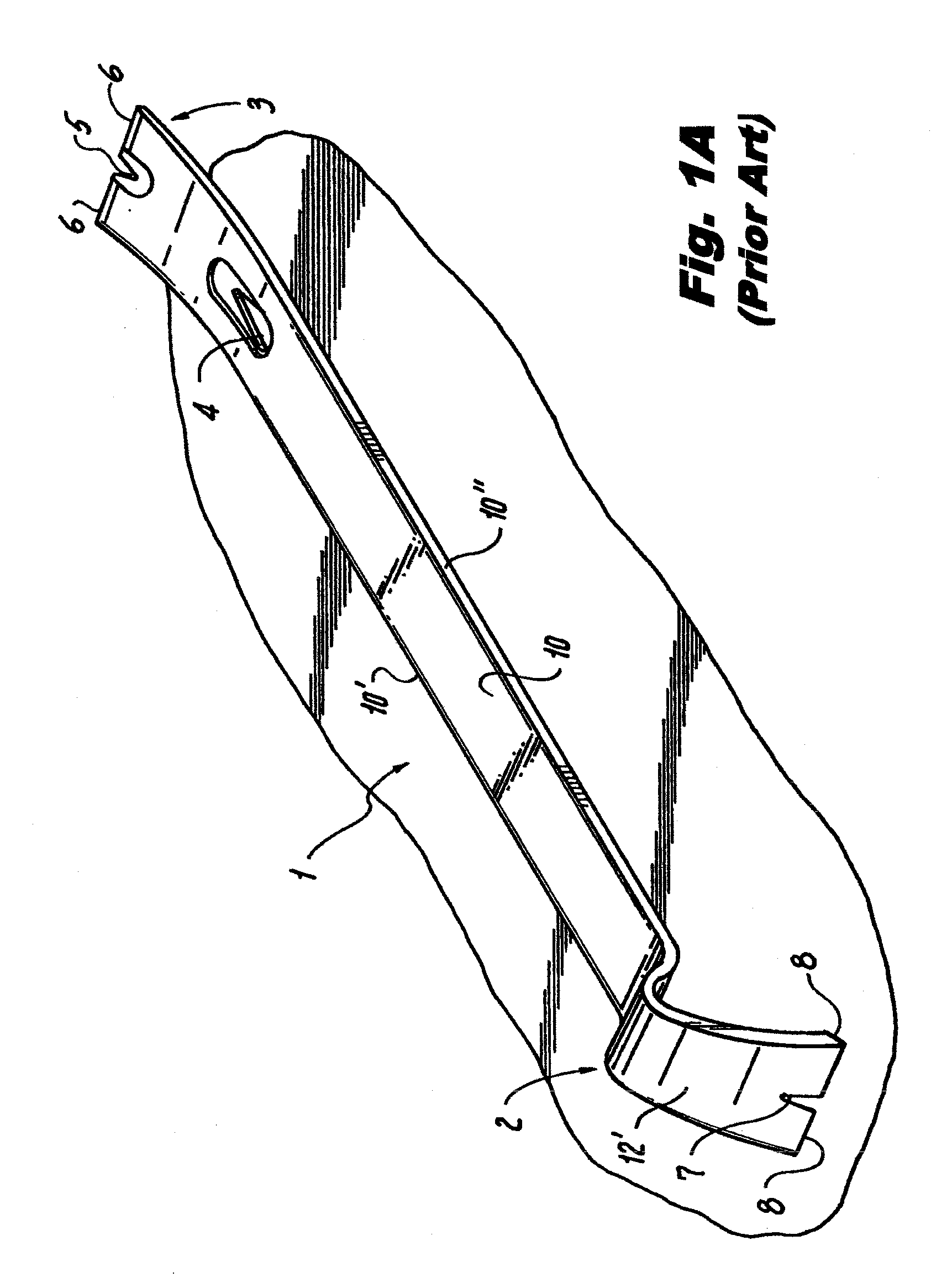
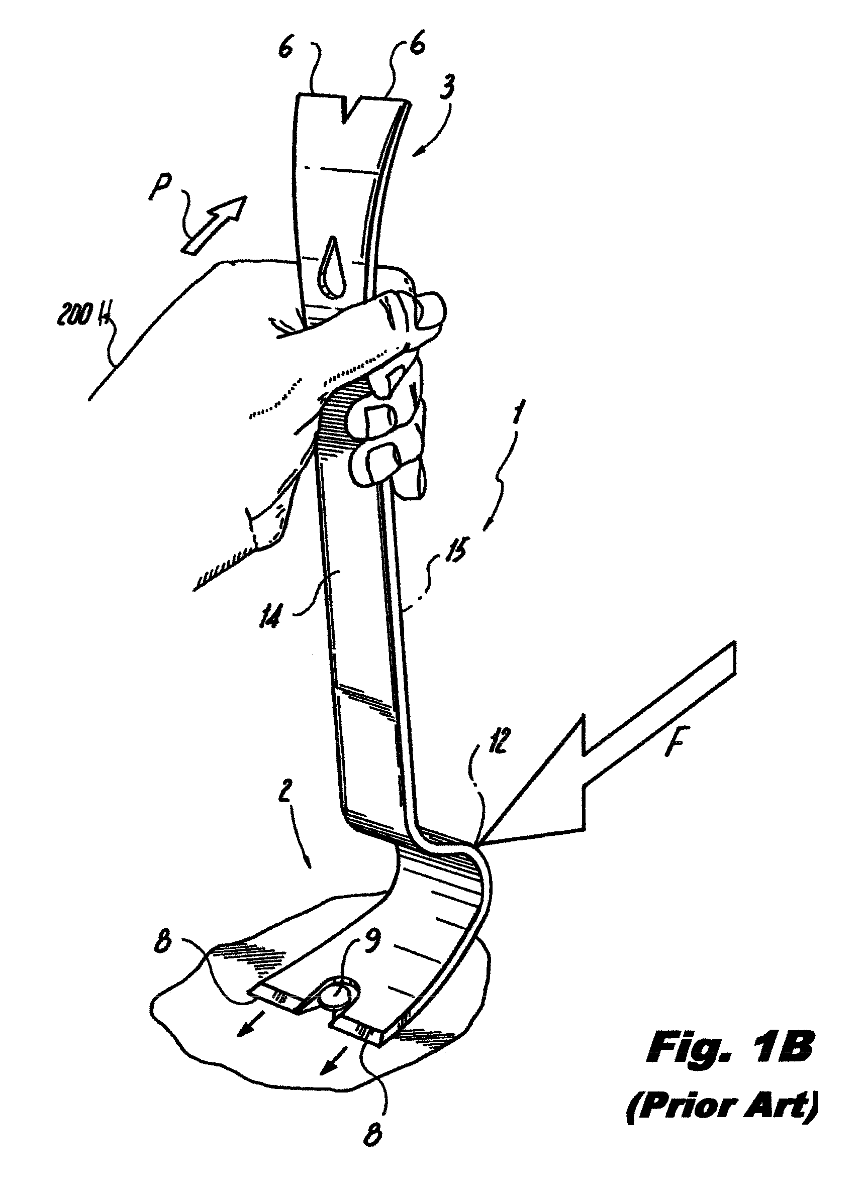
[0048]Reference will now be made in detail to several embodiments of the invention that are illustrated in the accompanying drawings. Wherever possible, same or similar reference numerals are used in the drawings and the description to refer to the same or like parts or steps. The drawings are in simplified form and are not to precise scale. For purposes of convenience and clarity only, directional terms, such as top, bottom, up, down, over, above, and below may be used with respect to the drawings. These and similar directional terms should not be construed to limit the scope of the invention in any manner. The words “connect,”“couple,” and similar terms with their inflectional morphemes do not necessarily denote direct and immediate connections, but also include connections through mediate elements or devices.

[0049]Referring generally to FIGS. 2A to 2D, and specifically now to FIG. 2A, a combination hand tool bar 100 is provided having a pry end 102 and a distal hook end 101 space...


PUM

PropertyMeasurementUnit
angleaaaaaaaaaa
angleaaaaaaaaaa
angleaaaaaaaaaa

Abstract

In accordance with the present invention, there is provided a combination hand tool bar device suitable for pulling nails and other materials from surfaces, with improved user ergonomics and efficient force transfer. The device includes a hook end and a pry end joined by a bar shank member interposed there between. The hook end further comprises a compound curve projecting in the same direction from the bar shank member as the pry end enabling an increased user throw and ergonomic comfort.

Description

CROSS REFERENCE TO RELATED APPLICATION(S)[0001]This application relates to and claims priority from U.S. Prov. Ser. No. 60 / 893,018 filed Mar. 5, 2007, the entire contents of which are herein incorporated by reference.BACKGROUND OF THE INVENTION[0002]1. Field of the Invention[0003]The present invention relates generally to a nail-pulling device having combined nail-pulling ends. More specifically, the present invention relates to a combination prying and nail-pulling device that provides a user with improved comfort, leverage, and overall ergonomic success, as well as to a method for employing the device to effect nail removal[0004]2. Description of the Related Art[0005]The related art involves the use of traditional tools to pry materials from surfaces such as nails affixed to flooring, walls, or roofing.[0006]Using traditional tools, the nails are removed from such surfaces with a claw hammer or similar device. Optionally, a standard crowbar or other prying tool is used to pry the ...

Claims


Application Information

Patent Timeline
Patent Type & Authority Applications(United States)
IPC IPC(8): B25C11/00B66F15/00B23P19/04
CPCY10T29/53B25C11/00
Inventor CHAMBERS, DANIEL
Owner VAUGHAN & BUSHNELL MANUFACTURING
Why Eureka
Try Eureka