Kite Power Generator

a power generator and kite technology, applied in the direction of electric generator control, machines/engines, mechanical equipment, etc., can solve the problems of economic and engineering limitations, unsightly appearance, and expensive construction, and achieve the effects of convenient disassembly, improved reliability, and improved construction efficiency

Inactive Publication Date: 2008-09-25
NICHOLSON KIT +2
View PDF9 Cites 30 Cited by
  • Summary
  • Abstract
  • Description
  • Claims
  • Application Information

AI Technical Summary

Problems solved by technology

This means that they have to be large structures, which are often considered unsightly.
They are also expensive to construct and there are economic and engineering limits to the height of the towers and hence to the ability to harness faster and more reliable winds at higher altitudes.
It is also claimed that the rotating blades can harm birds in flight.

Method used


Image

  • Kite Power Generator
  • Kite Power Generator
  • Kite Power Generator

Examples


Embodiment Construction

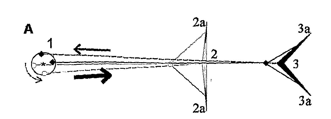
[0024]Kitepower generators use one or more kites that are connected by one or more lines to a device on the ground that converts a pattern of forces in the kite lines into a movement from which power can be generated. Kites are defined as objects that are flown in the air or in other gases or fluids, such as water, on the end of one or more tether lines, using wind to create a pull on the line.

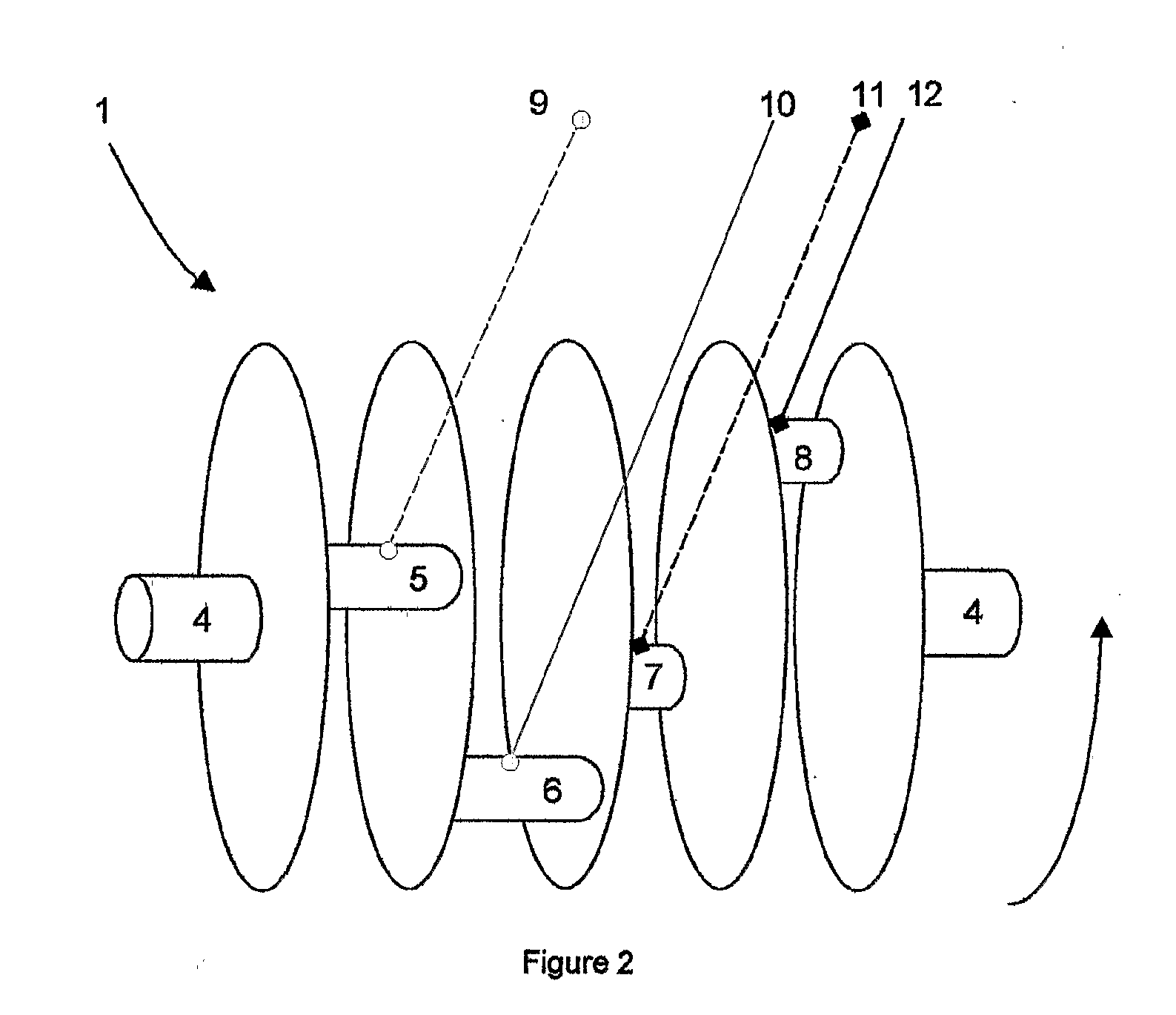
[0025]In most cases, the movement from which power can be generated is rotational, and the conversion device may be called a rotatable device. One useful version of the rotatable device is a crankshaft, which is defined as a structure that allows a set of crankpins to rotate around an axis of rotation without the need for an axle running through the axis of rotation. However, other movements may also be used, such as a see-saw motion on one or more levers.

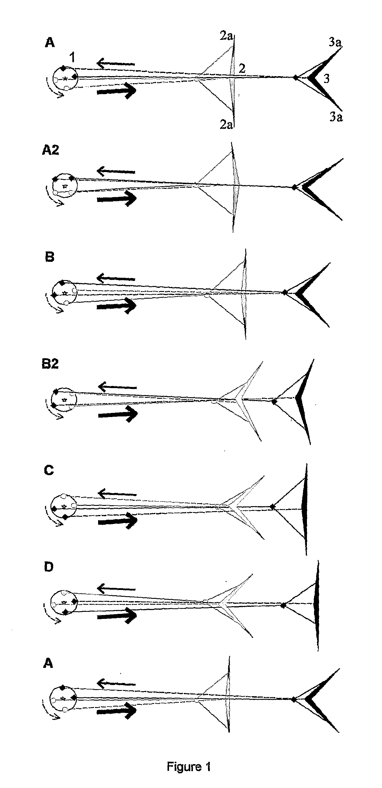
[0026]There are a number of different options for the cycle of motion in the kite(s). All these options involve changes in the pull of the k...


PUM


Abstract

The Kitepower Generator uses one or more kites that go through a oscillating cycle of motion creating varying forces on their tether lines. These varying forces are converted into rotation, using a crankshaft. The cycle of motion may be driven by the inherent kite design or through the action of two or more tether lines connected to a crankshaft. The pull from the lines is stronger when they pull out and weaker when they are being pulled in. The cycle of motion may involve flapping, swirling, waving, swooping, veering or feathering. Several kites may be connected or combined into a single composite kite. Efficiency is higher with three or more lines so that one is always pulling out strongly. Various techniques keep kites aloft in still or stormy weather.

Description

BACKGROUND[0001]Conventional wind turbines generate power from rotating blades mounted on towers. This means that they have to be large structures, which are often considered unsightly. They are also expensive to construct and there are economic and engineering limits to the height of the towers and hence to the ability to harness faster and more reliable winds at higher altitudes. It is also claimed that the rotating blades can harm birds in flight.[0002]It is an object of the present invention to obviate or mitigate at least one of the problems associated with the prior art.STATEMENT OF INVENTION[0003]According to a first aspect of the present invention there is provided a range of kites that generate varying patterns of forces on the tether or tethers to which they are connected.[0004]Preferably, these kites involve a pattern of forces that is generated by: flapping; swirling; waving; spinning; changing angle of attack; feathering or venting, moving in a repeated path through the...

Claims


Application Information

Patent Timeline
Patent Type & Authority Applications(United States)
IPC IPC(8): F03D5/06
CPCF03D5/00F05B2210/16Y02E10/70F05B2240/921F05B2260/40F05B2240/40
Inventor NICHOLSON, KITNICHOLSON, HAMISHRICKETTS, MARC
Owner NICHOLSON KIT
Why Eureka
Try Eureka