
Headlight Apparatus and Vehicle

a headlight and lens technology, applied in the field of headlight apparatuses, can solve the problems of increasing manufacturing costs, complicated predetermined projections and depressions on the inner surface and inability to reduce the thickness of the flasher lens in order to reduce the weight of the headlight apparatus

Inactive Publication Date: 2008-10-02
YAMAHA MOTOR CO LTD
View PDF10 Cites 18 Cited by
  • Summary
  • Abstract
  • Description
  • Claims
  • Application Information

AI Technical Summary

Benefits of technology

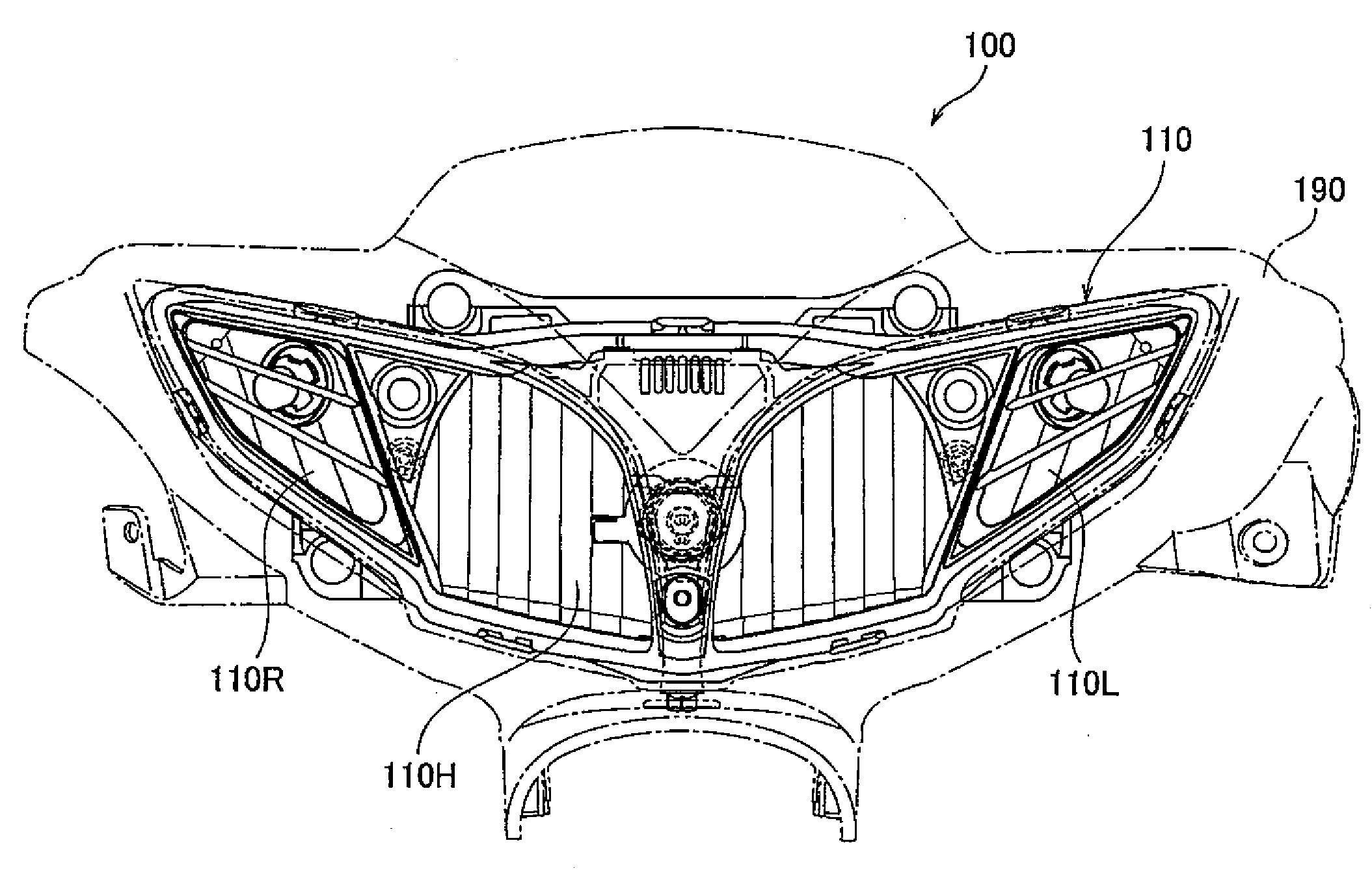
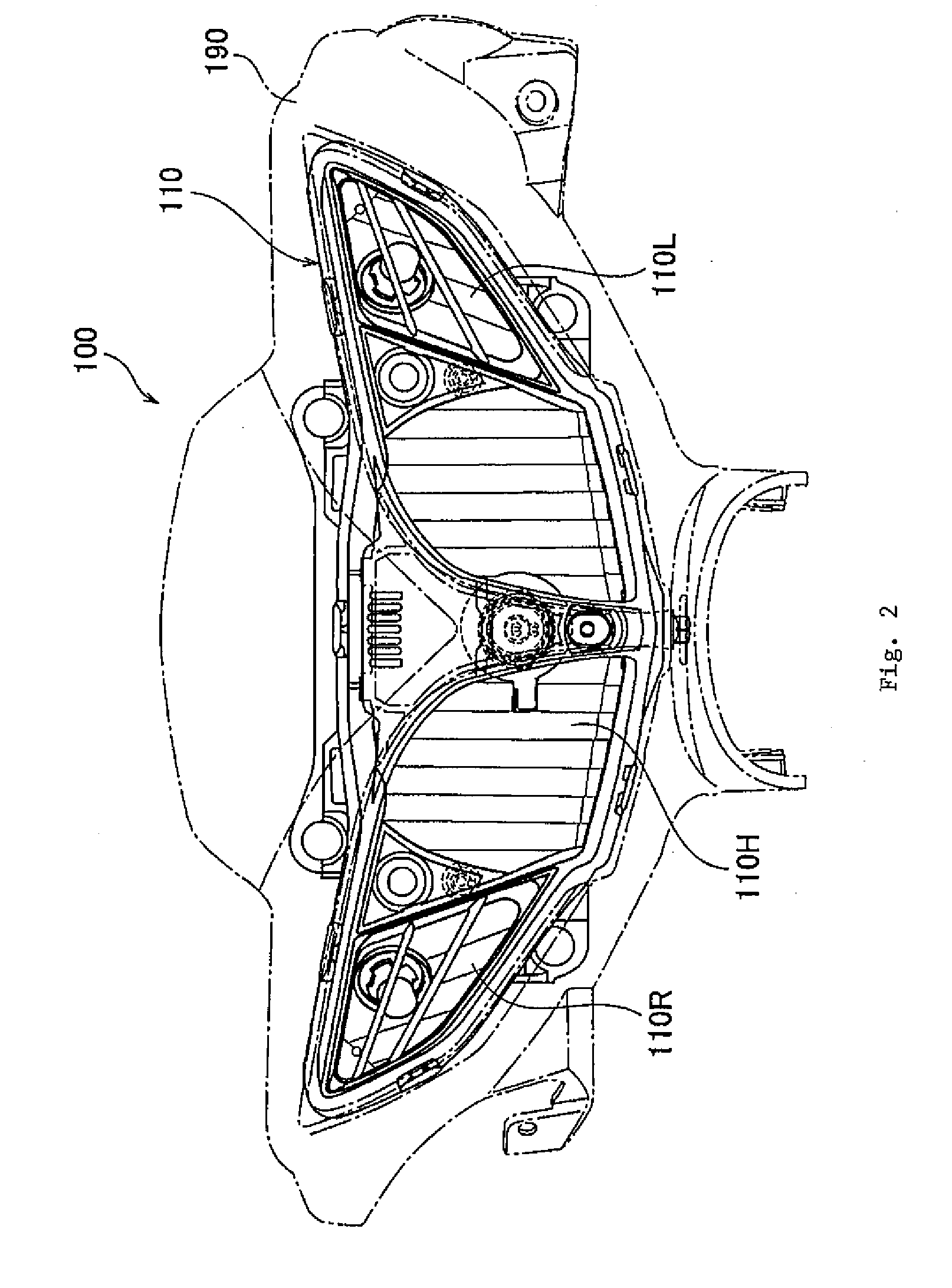
The present invention provides a headlight apparatus for a vehicle that allows adjustment of luminous energy and a traveling direction of light emitted from a flasher bulb without applying a work on an inner surface of a flasher lens. The headlight apparatus includes a directional indicator with a light source and a partition on the inner surface of the directional indicator lens that can adjust the luminous energy and the traveling direction of the light emitted from the flasher bulb. The directional indicator is adjacent to the headlight and the partition has a flat plate or multiple plate portions and an outer frame portion that supports the plate portions. The optical axis of the light source extends obliquely forwardly from the vehicle to which the headlight apparatus is attached. The technical effects of the invention include improved adjustability of the headlight without damaging the flasher lens and improved lighting performance.

Problems solved by technology

The aforementioned conventional headlight apparatus has a problem in that the flasher lens must be thicker than a predetermined thickness to allow the predetermined projections and depressions to be formed on the inner surface of the lens.
Therefore, the ability to reduce the thickness of the flasher lens in order to reduce the weight of the headlight apparatus is limited.
Furthermore, there is another problem in that the process of forming the predetermined projections and depressions on the inner surface of the flasher lens is complicated and increases manufacturing costs.

Method used


Image

  • Headlight Apparatus and Vehicle
  • Headlight Apparatus and Vehicle
  • Headlight Apparatus and Vehicle

Examples


Embodiment Construction

Configuration of Vehicle According to Present Embodiment

[0027]An embodiment of a vehicle according to the present invention is now described with reference to the drawings. In the following description and drawings, identical or similar parts are denoted by identical or similar reference numerals. It should also be noted that the drawings are schematic diagrams, and may represent different dimensional ratios and the like from those of the actual apparatus.

[0028]Hence, specific dimensions and the like should be determined in consideration of the following description. Furthermore, as a matter of course, different drawings include elements which have different dimensional relations and ratios.

[0029](1) General Configuration

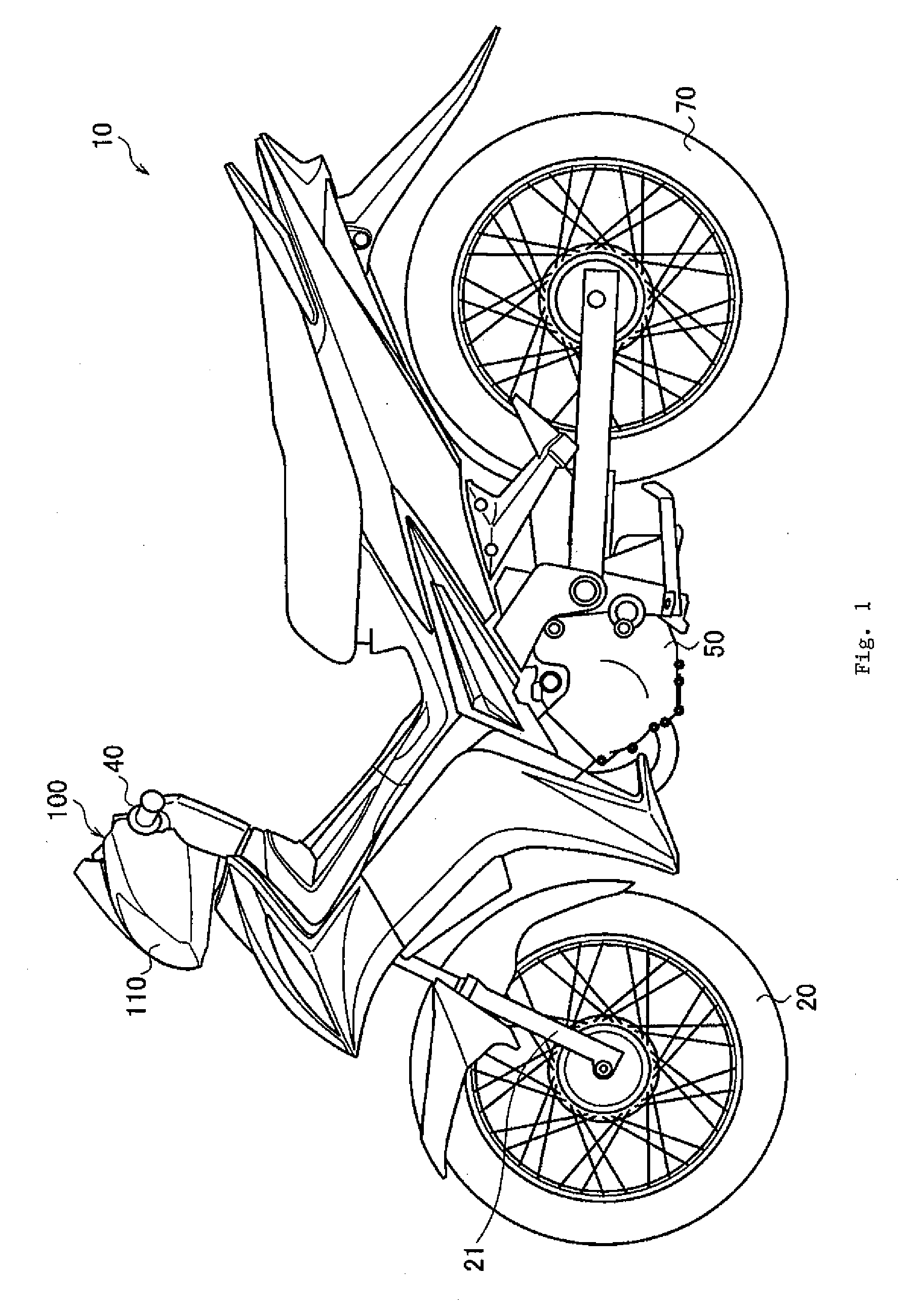
[0030]FIG. 1 is a left side view of a motorcycle 10. Motorcycle 10 is a so-called underbone-type motorcycle having a body frame disposed at a lower position as compared with that of a general straddle-type motorcycle.

[0031]Motorcycle 10 has a front wheel 20 and a re...


PUM


Abstract

A headlight apparatus that adjusts the luminous energy and traveling direction of light emitted from a flasher bulb without applying a machining on an inner surface of a flasher lens. A headlight unit includes a flasher bulb that flashes at predetermined intervals, and a flasher lens. The headlight unit has a louver that partitions the flasher lens. The louver is disposed on an inner surface of the flasher lens.

Description

RELATED APPLICATIONS[0001]This application claims the benefit of priority under 35 USC 119 of Japanese patent application nos. 2006-269999, filed on Sep. 29, 2006, which application is hereby incorporated by reference in its entirety.BACKGROUND OF THE INVENTION[0002]1. Field of the Invention[0003]The present invention relates to a headlight apparatus having a headlight and a directional indicator, and to a vehicle having the headlight apparatus.[0004]2. Description of Related Art[0005]A headlight apparatus is provided in a front portion of a vehicle, such as a motorcycle, e.g., in front of a handlebar.[0006]In known configurations, a directional indicator, or a flasher lamp, is disposed on each outer side of a headlight to indicate a change in traveling direction of the vehicle (see, e.g., JP-Y-2547379 (page 3 and FIG. 1)).[0007]A flasher lamp of this type generally has a flasher bulb that flashes at predetermined intervals and a flasher lens disposed forward of the flasher bulb. Pr...

Claims


Application Information

Patent Timeline
Patent Type & Authority Applications(United States)
IPC IPC(8): B62J6/00
CPCB60Q1/0041B62J6/026B62J6/055
Inventor AOKI, YASUSHI
Owner YAMAHA MOTOR CO LTD
Learn More