Extension Photoflash Light and Camera System Using the Same

a technology of flash light and extension light, which is applied in the field of extension flash light and camera system using the same, can solve the problems of not being able to provide the light source sufficient to properly expose the photosensitive members, and the performance of the built-in digital camera in the low-light or backlight environment cannot match with the conventional digital camera,

Inactive Publication Date: 2017-10-05
YANG STEVE WIYI
View PDF0 Cites 5 Cited by
  • Summary
  • Abstract
  • Description
  • Claims
  • Application Information

AI Technical Summary

Benefits of technology

[0011]In the extension photoflash light and the camera system using the same according to the preferred embodiment of the invention, when the mounting mechanism of the extension photoflash light touches a surface of the flat panel display of the mobile device with the photographing function, the mobile device with the photographing function obtains the mounting position of the extension photoflash light according to a distance between touch points and theirs touch time. In another preferred embodiment, the touch simulation device is further used for outputting a touch signal, wherein the mobile device with the photographing function decodes the touch signal output from the touch simulation device to obtain a received message according to whether touch is detected by the mobile device or not such that a state of the extension photoflash light is determined. In a preferred embodiment, the state of the extension photoflash light includes residual capacity information of a battery. In another preferred embodiment, the state of the extension photoflash light comprises information regarding whether the HID lamp is completely charged. In another preferred embodiment, the state of the extension photoflash light comprises a brand information.
[0014]The essence of the invention is to provide an extension photoflash light that can be mounted on the mobile device, wherein a touch simulation device is disposed on the mounting mechanism of the extension photoflash light. Through the touch simulation device, the mobile device can obtain the mounting position of the extension photoflash light. Moreover, in this embodiment, the extension photoflash light can also report brand information, residual capacity information of a battery, the charging state and / or the information of the extension photoflash light by the touch simulation device. Thus, the extension photoflash light can communicate with the mobile device.

Problems solved by technology

However, the performances of these built-in digital cameras in the low-light or backlight environment cannot match with the conventional digital camera.
Although each of some mobile devices with built-in digital cameras is also equipped with a light-emitting diode (LED) assistant exposure light, the assistant exposure amount of the LED assistant exposure light is seriously restricted due to the battery capacity of the mobile device and the heat dissipating problem of the LED.
When the distance to the to-be-illuminated object exceeds 1 meter, the LED cannot provide the sufficient light source to properly expose the photosensitive members.
These capacitors have the very large volume, and cannot be accepted by the mobile device under the slim and light preconditions of the mobile device.
However, due to the limitation of the rolling shutter, the flash time of the xenon photoflash light is only several microseconds (μs), which is relatively short, and the extension xenon photoflash light often cannot find the optimum flash timing.
The HID lamp cannot perform flash operation if HID lamp is not sufficiently charged.

Method used


Image

  • Extension Photoflash Light and Camera System Using the Same
  • Extension Photoflash Light and Camera System Using the Same
  • Extension Photoflash Light and Camera System Using the Same

Examples


Embodiment Construction

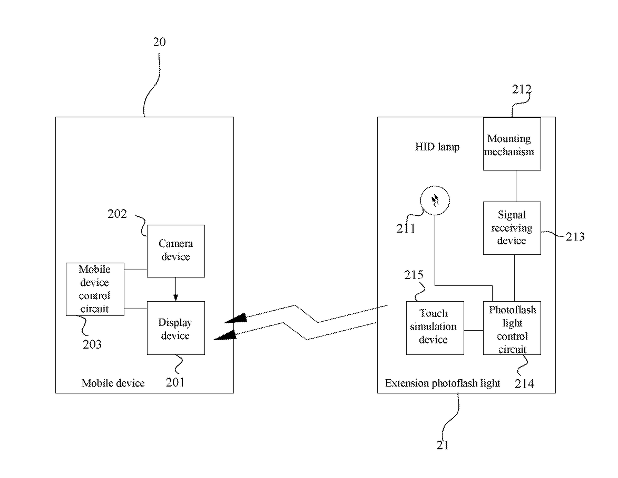
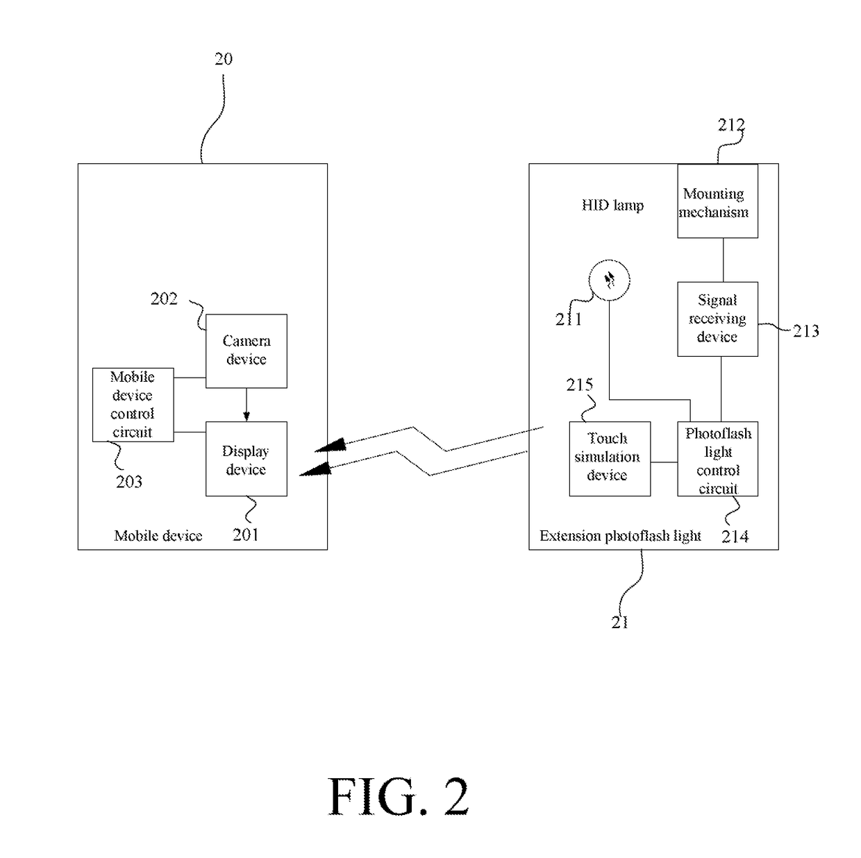
[0030]FIG. 2 is a system block diagram showing a camera system according to a preferred embodiment of the invention. Referring to FIG. 2, the camera system comprises a mobile device 20 and an extension photoflash light 21. The mobile device 20 comprises a display device 201, a camera device 202 and a mobile device control circuit 203. The extension photoflash light 21 comprises a HID lamp 211, a mounting mechanism 212, a signal receiving device 213, a photoflash light control circuit 214 and a touch simulation device 215.

[0031]The mounting mechanism 212 is for mounting or hanging the extension photoflash light 21, the detailed structure of which will be described later. The signal receiving device 213 in this embodiment is for example implemented by a light sensing circuit, and the signal receiving device 213 is disposed on the mounting mechanism 212 and for sensing a light signal outputted from the display device 201 of the mobile device 20. The photoflash light control circuit 214...


PUM


Abstract

An extension photoflash light and a camera system using the same are provided in the present invention. The extension photoflash light is for assisting a mobile device with camera function. The extension photoflash light includes a HID, a mounting mechanism, a touch simulation device and a control circuit. The mounting mechanism is for mounting the extension photoflash light on the mobile device. The touch simulation device is disposed on the mounting mechanism. The control circuit is coupled to the HID and the touch simulation device. When the mounting device of the extension photoflash light contacts the surface of the flat panel display of the mobile device, the mobile device acquire the position information of the extension photoflash light according to the touch simulation device.

Description

[0001]This application claims priority to U.S. Provisional Patent Application Ser. No. 62 / 317,062 filed on Apr. 1, 2016 which is incorporated herein by reference in its entirety.BACKGROUND OF THE INVENTIONField of the Invention[0002]The invention relates to the technology of a photoflash light used in a mobile device, and more particularly to an extension photoflash light and a camera system using the same.Description of the Related Art[0003]Due to the progresses of the pixel and quality of the digital photographing, a mobile device (e.g., a mobile phone or a tablet computer) possessing the photographing function has become a trend. However, the performances of these built-in digital cameras in the low-light or backlight environment cannot match with the conventional digital camera. Although each of some mobile devices with built-in digital cameras is also equipped with a light-emitting diode (LED) assistant exposure light, the assistant exposure amount of the LED assistant exposure...

Claims


Application Information

Patent Timeline
Patent Type & Authority Applications(United States)
IPC IPC(8): H04N5/225G03B15/04F21K5/16F21K5/06G03B15/05H05B37/02H04N5/232G03B30/00
CPCH04N5/2256H05B37/0218G03B15/041H04N5/23293F21S9/02G03B15/0447H04N5/23241G03B15/05G03B15/0473H04N5/23203H04N23/56H04N23/65H04N23/63H04N23/71H05B41/32G03B17/566H05B47/19Y02B20/40H04N23/66H04N23/631H04N23/74H05B47/11H05B41/36
Inventor YANG, STEVE WIYI
Owner YANG STEVE WIYI
Why Eureka
Try Eureka