Voltage bucking circuit for driving flashlamp-pumped lasers for treating skin

a voltage bucking circuit and laser technology, applied in the field ofdermatological lasers, can solve the problems of complex system, limited number of capacitors used in a series of energy storage capacitors, and energy delivered in each laser sub-pulse needs to be adjusted, so as to achieve high current modulation, simple and compact driving circuit configuration, and rapid dye replacement

Active Publication Date: 2013-12-24
CANDELA CORP
View PDF56 Cites 7 Cited by
  • Summary
  • Abstract
  • Description
  • Claims
  • Application Information

AI Technical Summary

Benefits of technology

[0017]Advantages of the invention can include one or more of the following. The number of sub-pulses capable of being produced by the flashlamp driver circuit is not limited by, for example, the number of capacitors. The driving circuit configuration is also simple and compact. In addition, the high level of current modulation obviates the need for rapid dye replacement in a dye-laser system. Furthermore, an IGBT can be operated at a reasonable frequency so that the switching losses are moderate. The system can also be operated in a quasi-CW mode. In addition, the present invention allows for more efficient and accurate control of the output laser power. Furthermore, control of the output laser power can be based in real-time.
[0018]The present invention can also be advantageously used to drive the flashlamp used in devices (e.g., intense pulse light (IPL) devices) where the flashlamp radiation is used directly to treat the skin after the lamp's emission spectrum has been modified by spectral filters. For example, the present invention can be used in IPL devices to maintain a constant flashlamp current, such that the output spectrum of the lamp can be held constant.

Problems solved by technology

Most of the heat is confined to the vessel and so it is damaged while most of the surrounding tissue is spared.
The maximum number of sub-pulses in a driving configuration, however, using a series of energy storage capacitors is limited to the number of capacitors.
Another disadvantage is that, in practice, the energy delivered in each laser sub-pulse needs to be adjusted individually for the desired output energy.
This system becomes complex and difficult to calibrate for a large numbers of sub-pulses.
The problem with this circuit is that the capacitor voltage drops during the pulse.
This is a problem for lasers, such as pulsed dye lasers, that suffer a drop in the laser efficiency during a single pulse and in each subsequent sub-pulses due to thermal and other degradations in the lasing medium.

Method used


Image

  • Voltage bucking circuit for driving flashlamp-pumped lasers for treating skin
  • Voltage bucking circuit for driving flashlamp-pumped lasers for treating skin
  • Voltage bucking circuit for driving flashlamp-pumped lasers for treating skin

Examples


Embodiment Construction

[0027]Lasers and other light sources are often used for the treatment of skin disorders and to improve the appearance of the skin. The heat produced by the light energy can modify structures within the skin and beneath the skin. Typical applications can include, for example, removal of hair, pigmented lesions, tattoos, vascular lesions, wrinkles, acne, skin tightening, and / or the like. Lasers are often the preferred light source because a laser beam has a narrower wavelength bandwidth than light from other sources. In addition, lasers can be made with much shorter pulse durations than other light sources, thereby maximizing the temporal selectivity of the targeted structure.

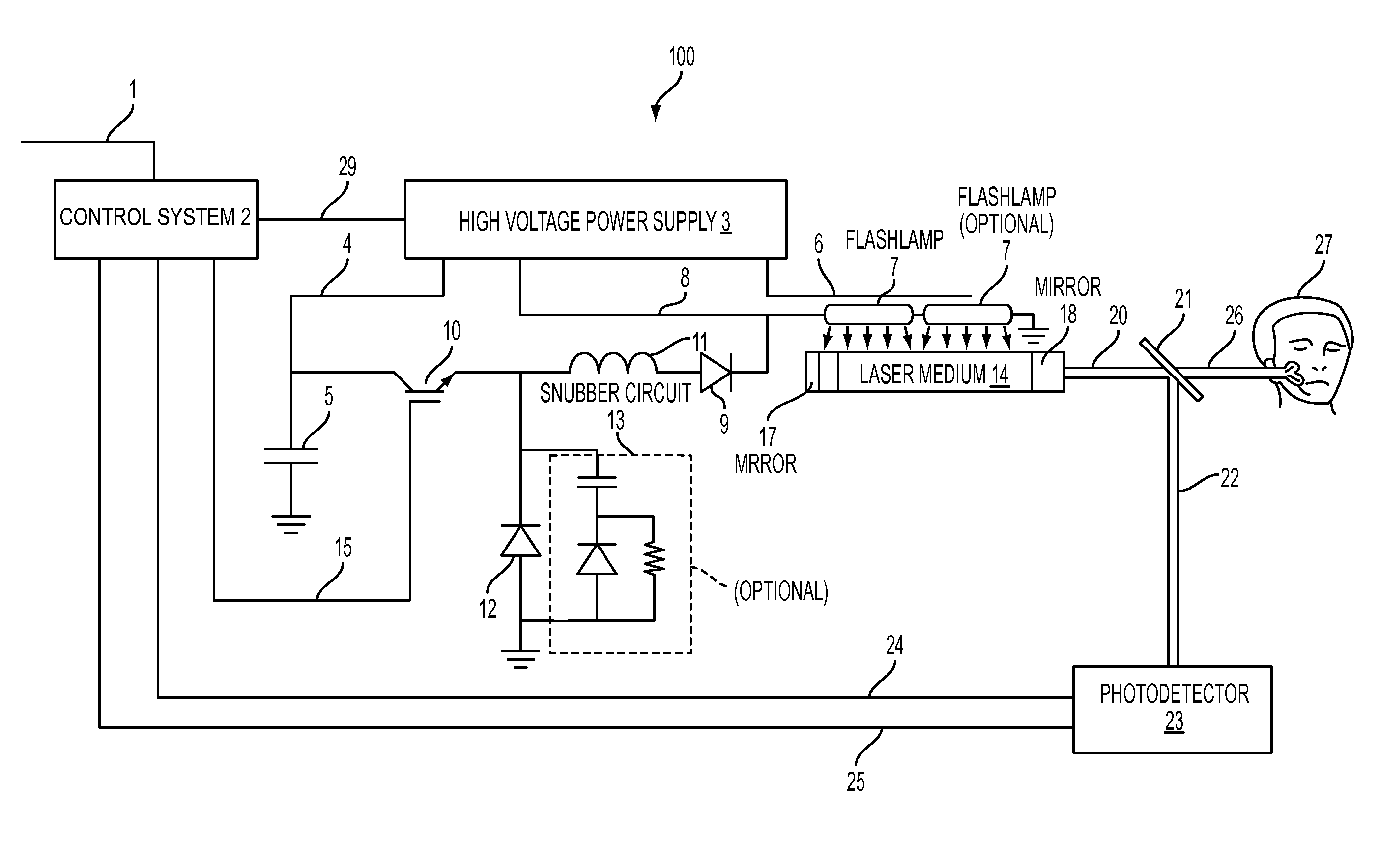
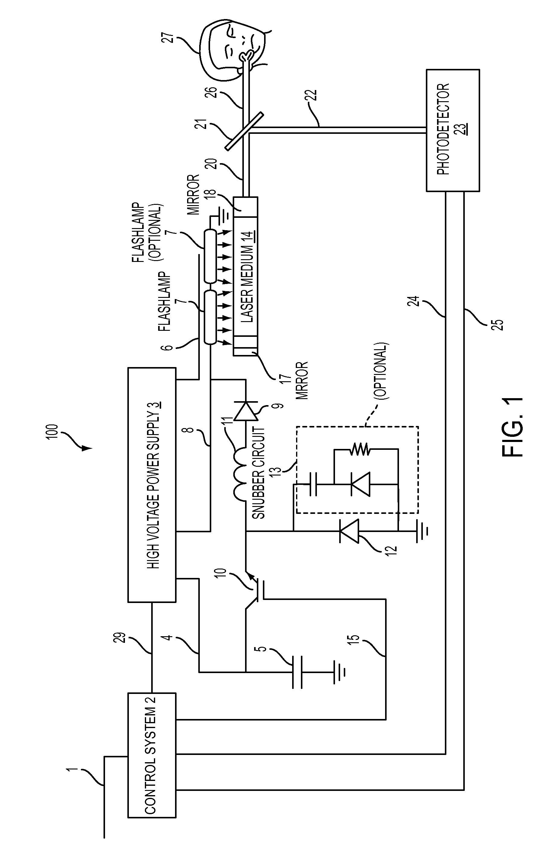
[0028]FIG. 1 illustrates one embodiment of a system 100 including an electrical circuit capable of driving one or more flashlamps to pump a laser. A flashlamp 7 is driven with an insulated gate bipolar transistor (IGBT) 10, an inductor 11 and a diode 12 connected in a voltage bucking configuration. The flashlamp ...


PUM


Abstract

Described is a device for driving a dermatological laser. The system includes a first diode, an inductor, a switch, and a photodetector. A first end of the inductor is coupled to an end of the first diode, and a second end of the inductor is coupled to a flashlamp. An electrical control of the switch is coupled to a control system, a first end of the switch is coupled to a power source, and a second end of the switch is coupled to the first end of the inductor and the end of the first diode. The photodetector is adapted to measure at least one of output energy or output power of a laser medium pumped by the flashlamp. The photodetector is in communication with the control system for modulating a flashlamp that drives current to maintain a predetermined value of the measured output energy or output power.

Description

CROSS-REFERENCE TO RELATED APPLICATION[0001]This application claims the benefit of and priority to U.S. Provisional Application Ser. No. 60 / 850,755 filed Oct. 11, 2006, which is owned by the assignee of the instant application and the disclosure of which is incorporated herein by reference in its entirety.FIELD OF THE INVENTION[0002]The invention relates generally to a dermatological laser. In particular, the invention relates to a device that regulates the flashlamp current using a voltage bucking circuit configuration and a photodetector to measure the output of a laser. The circuit includes an inductor coupled to a diode and a switch for driving a flashlamp-pumped laser.BACKGROUND OF THE INVENTION[0003]Lasers are widely used in dermatological applications such as hair removal, removal of pigmented lesions, tattoos, vascular lesions, wrinkles, acne, and skin tightening. These and similar applications are effected by heating only a small structure in the skin to a temperature above...

Claims


Application Information

Patent Timeline
Patent Type & Authority Patents(United States)
IPC IPC(8): A61B18/18
CPCA61B18/203A61B2018/00458A61B2018/0047A61B2018/00476A61B2018/00702A61B2018/00779H01S3/092H01S3/10046H01S3/1024
Inventor JONES, CHRISTOPHER J.HSIA, JAMES C.MOGREN, SCOTT
Owner CANDELA CORP
Why Eureka
Try Eureka