

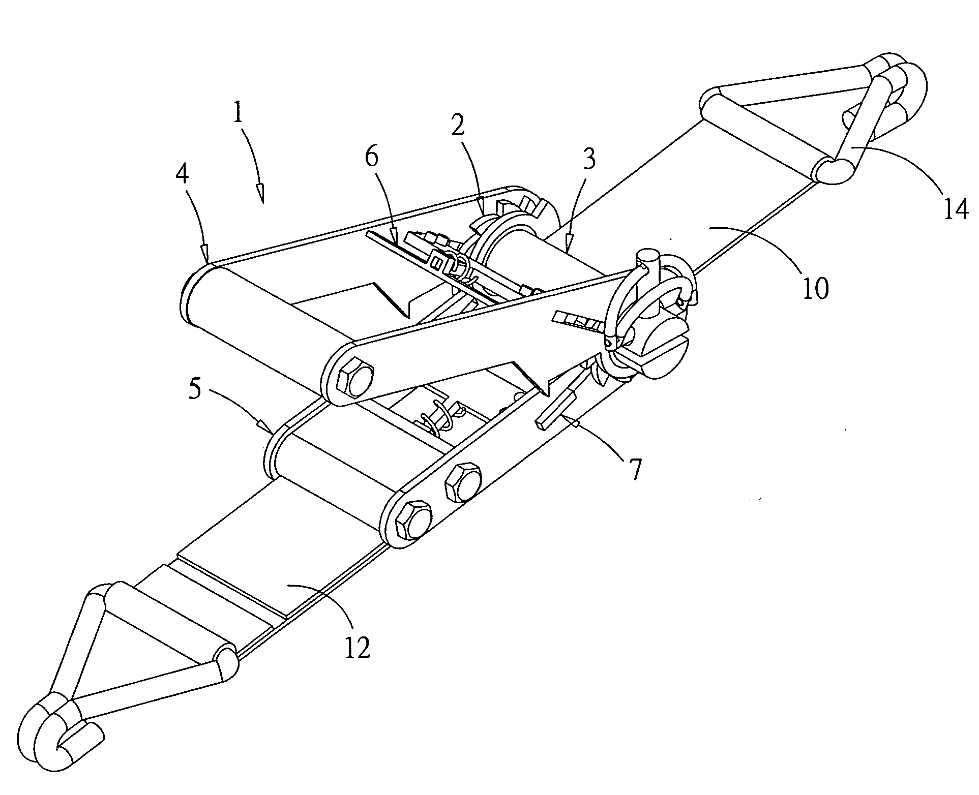
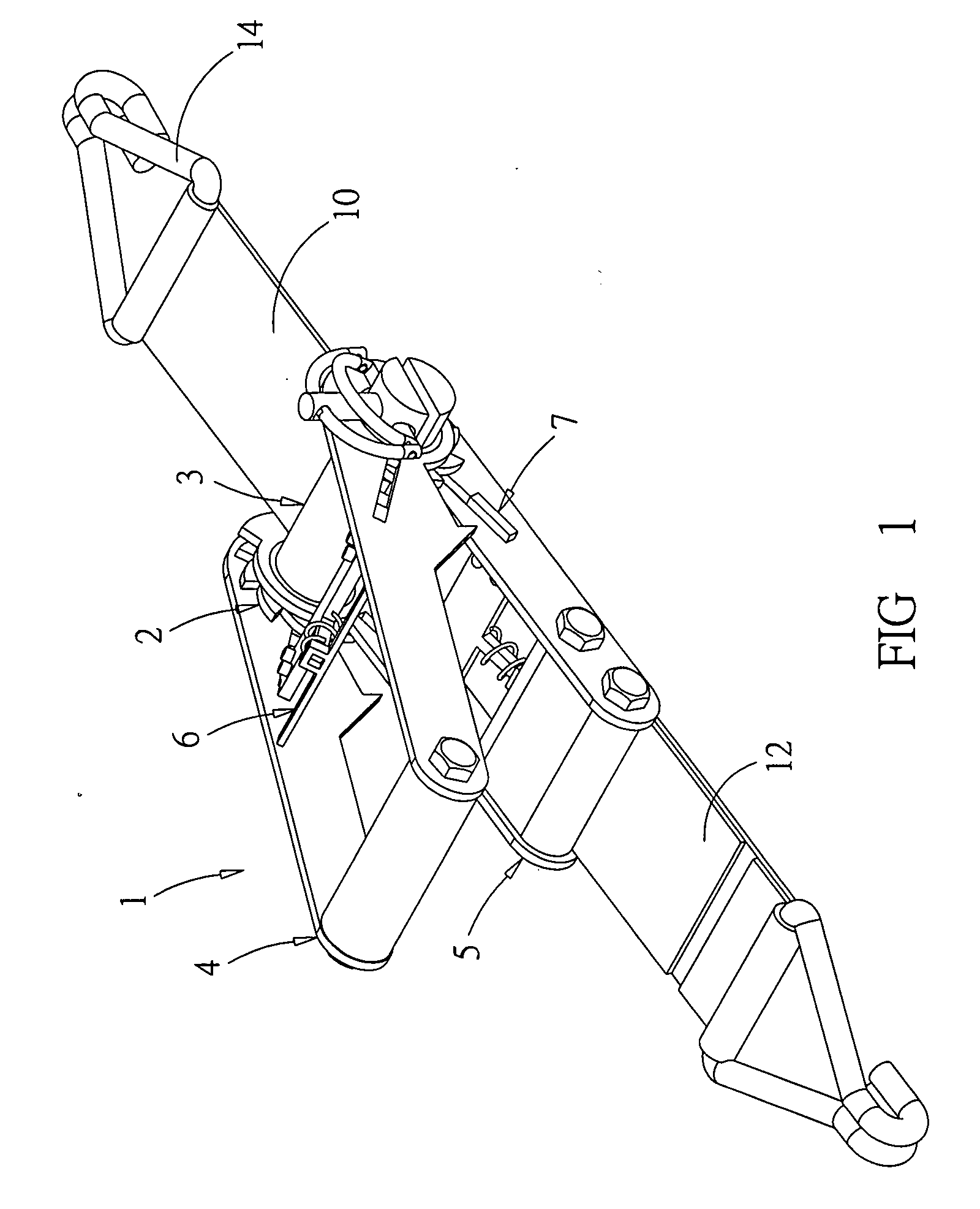
Binding device
a technology of a binding device and a mounting plate, which is applied in the direction of manufacturing tools, wire tools, transportation items, etc., can solve the problems of not being able to fix the latency of the latency in many cases, and achieve the effect of fast and convenient mounting
- Summary
- Abstract
- Description
- Claims
- Application Information
AI Technical Summary
Benefits of technology
Problems solved by technology
Method used
Image

Examples
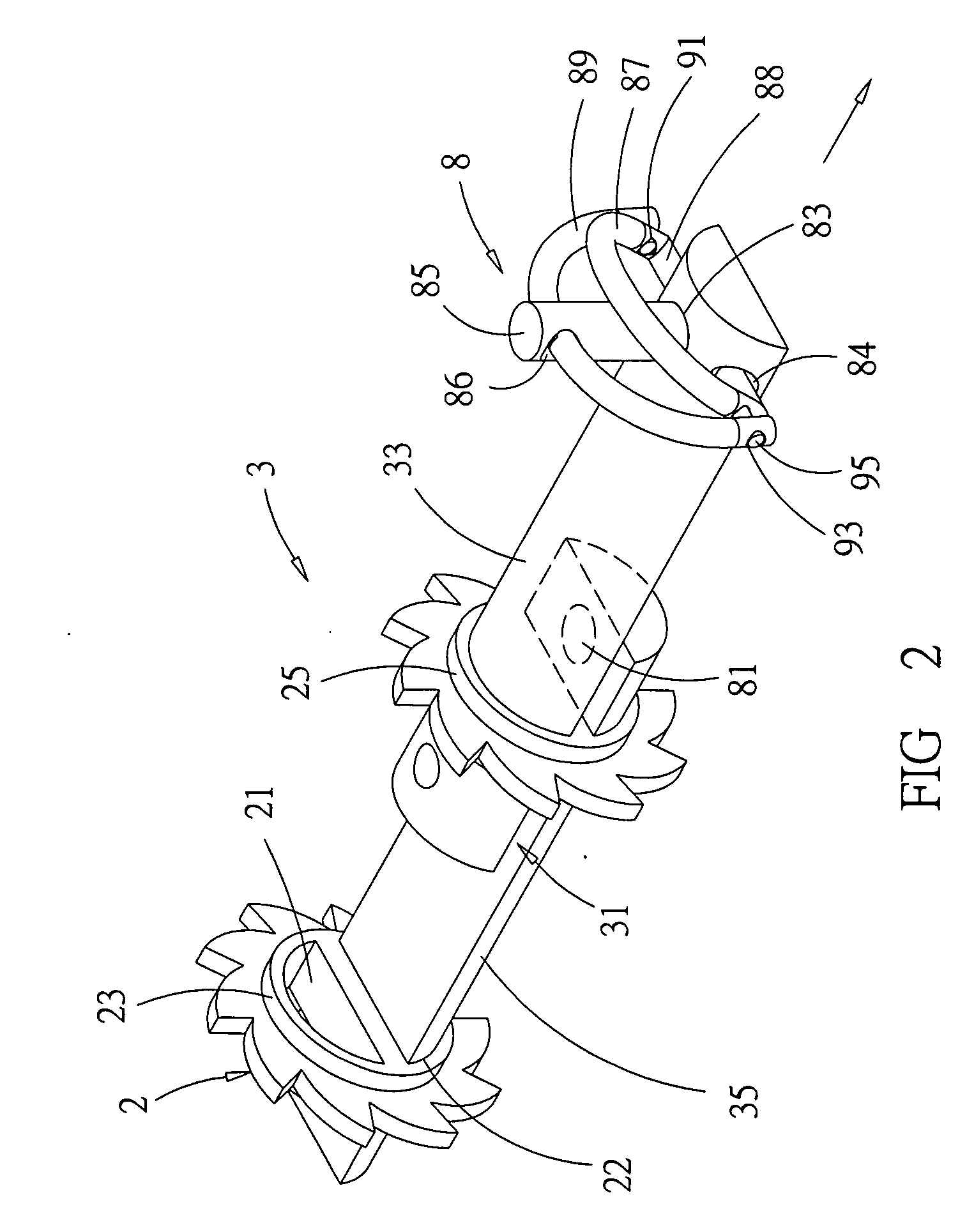
second embodiment
[0019]Referring to FIG. 3, the present invention in a second embodiment has two ratchet wheels 2b and a roll 3b with first and second roll sectors 33b, 35b which are both removable. On both ends of the roll 3b, a fixing assembly 8 is attached. For mounting the roll 3b, each of the ratchet wheels 2b has a support 27 with a mounting hole 29 into which the bolt 85 is inserted, so that the roll 3b is fixed.
third embodiment
[0020]Referring to FIG. 4, for saving manufacturing cost and more convenient production, the present invention in a third embodiment has ratchet wheels 2c, each comprising an inner half 20a with a circular inner protrusion 23c and an outer half 20b with a circular outer protrusion 25c.
[0021]The present invention offers the following advantages:
1. Fast mounting and dismounting of belts;
2. an extended range of applications;
3. no need for passing a belt through a gap and pulling out a belt therefrom;
4. saving manufacturing cost.
PUM
| Property | Measurement | Unit |
|---|---|---|
| force | aaaaa | aaaaa |
| width | aaaaa | aaaaa |
Abstract
Description
Claims
Application Information