Method of making a part and related system

a technology of a part and a connection, applied in the field of making a part, can solve the problems of reducing the cooling effect and as such the life of the actual part, not providing feedback, and the final part may not be as desired

Active Publication Date: 2008-10-16
PRATT & WHITNEY CANADA CORP
View PDF10 Cites 64 Cited by
  • Summary
  • Abstract
  • Description
  • Claims
  • Application Information

AI Technical Summary

Problems solved by technology

However, such an approach does not provide feedback as to whether the actual part is in the desired nominal location or has the desired nominal surface.
Thus, the final part may not be as desired.
In the case of gas turbine parts in which cooling holes are drilled, the airflow rate and its direction through

Method used


Image

  • Method of making a part and related system
  • Method of making a part and related system
  • Method of making a part and related system

Examples


Embodiment Construction

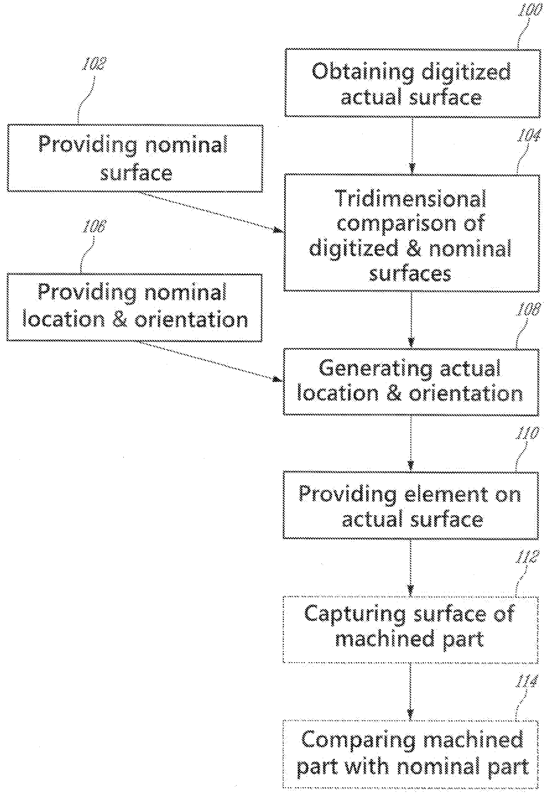
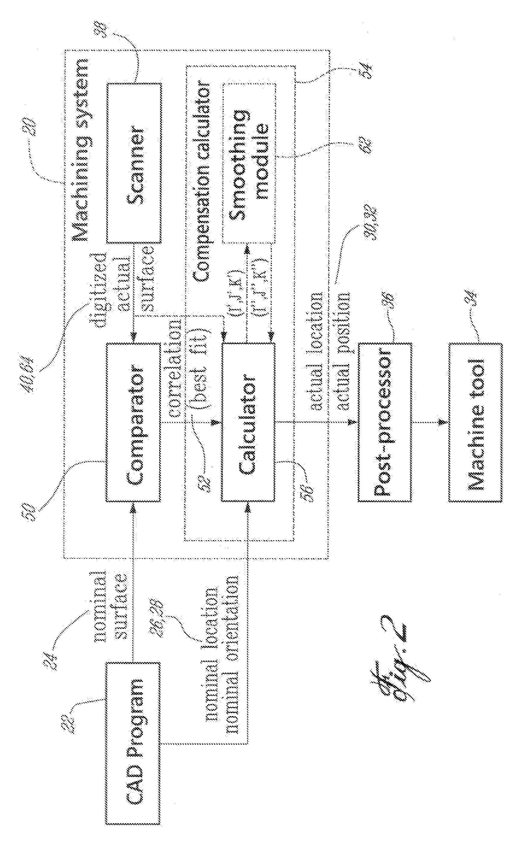
[0021]FIG. 2 illustrates an example of a machining system 20. The machining system 20 generally receives a nominal tridimensional definition of a part to be machined, for example in the form of a CAD file provided by a CAD program 22. The nominal tridimensional definition corresponds to a model of the entire part or of a tridimensional surface of the part and includes at least a nominal surface 24 of the part, as well as a nominal location 26 and a nominal orientation 28 of each of a plurality of geometrical elements machined on that surface.

[0022]In the present specification and claims, the terms “geometrical element” and “element” are intended to encompass all the features that define a part, such as for example a surface, profile, ellipse, diameter, angle, plane, slot, hole, groove, etc., as well as one or many surfaces that can be used as datum. The term “nominal” as applied to a part, surface, geometrical element, etc. is intended to refer to the part, surface, geometrical elem...


PUM

PropertyMeasurementUnit
Diameteraaaaaaaaaa
Sizeaaaaaaaaaa
Distanceaaaaaaaaaa

Abstract

A system and method of making a part, including capturing an actual tridimensional surface of each part to obtain a corresponding digitized actual surface, performing a tridimensional comparison between the digitized actual surface of each part and a nominal tridimensional surface, generating an actual location and orientation of an operation to be performed based on the tridimensional comparison, and performing the operation on the part based on the generated actual location and orientation of the element.

Description

TECHNICAL FIELD[0001]The invention relates generally to a method and system for compensating for differences between a nominal definition of a part and an actual part during a manufacturing process applied to the part.BACKGROUND OF THE ART[0002]When laser drilling holes or in other manufacturing processes, the machining tool must be positioned accurately with respect to the part being manufactured if the final part is to be made with any precision. In laser drilling, for example, the laser nozzle may be positioned in a nominal drilling location relative to a nominal surface of the part, the nominal drilling location being determined solely using a nominal computer model of the part, provided for example by a CAD (computer aided design) file. However, such an approach does not provide feedback as to whether the actual part is in the desired nominal location or has the desired nominal surface. Because of the differences between the actual surface and the nominal computer model of that...

Claims


Application Information

Patent Timeline
IPC IPC(8): G01D3/00
CPCG05B19/402G05B19/404G05B2219/36063G05B2219/37205Y10T29/49996Y10T29/49778Y10T408/03Y10T29/49Y10T29/49995G05B19/4097
Inventor BELLEROSE, MICHELBLAIS, MARIOING, VLSALBOUTHILLIER, ALAIN
Owner PRATT & WHITNEY CANADA CORP
Why Eureka
Try Eureka