
Multipart Sliding Joint For Floating Rig

a multi-part, floating rig technology, applied in the direction of sealing/packing, drilling pipes, well accessories, etc., can solve the problems of limited rig heave, unsuitable slip joints and interconnection methods of riser assemblies to floating rigs, and seals with considerable wear allowances, etc., to achieve the effect of large stroke length

Inactive Publication Date: 2008-10-16
HALLIBURTON ENERGY SERVICES INC
View PDF32 Cites 51 Cited by
  • Summary
  • Abstract
  • Description
  • Claims
  • Application Information

AI Technical Summary

Problems solved by technology

Unfortunately, typical slip joints and methods of interconnecting riser assemblies to floating rigs are unsuited for use with pressurized riser assemblies, and / or are suited for use only in very benign environments, for example, environments with very limited rig heave.
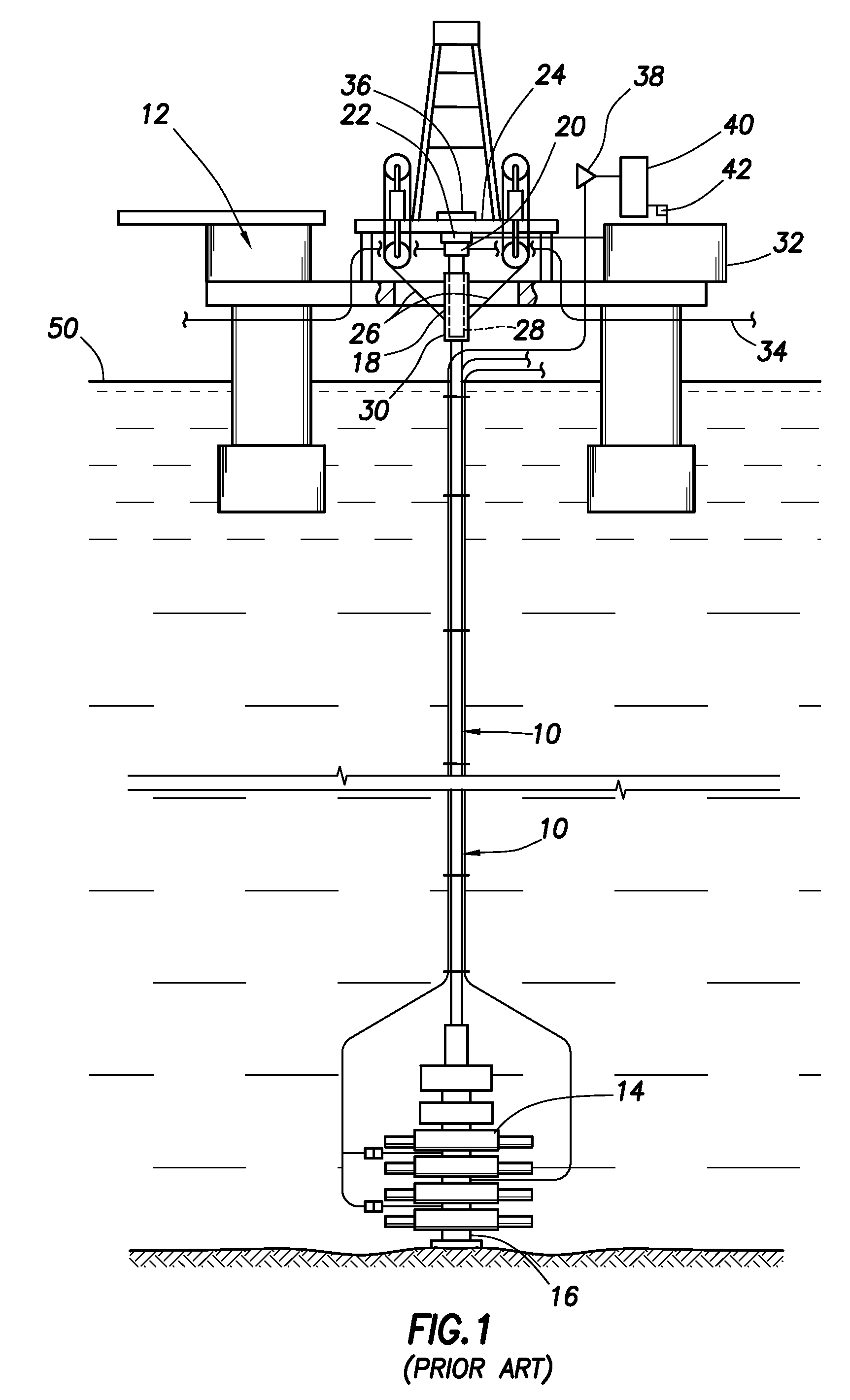
Seals may be provided between the inner and outer barrels 28, 30, but in the past these seals have only been designed for containing relatively low pressures (such as 500 psi), in substantial part due to large manufacturing tolerances, requiring large seals with considerable wear allowance.
In addition, the FIG. 1 example is unsuited for operations such as managed pressure drilling, in part because no rotating control device is provided to isolate the interior of the riser assembly 10 from the atmosphere at the surface.
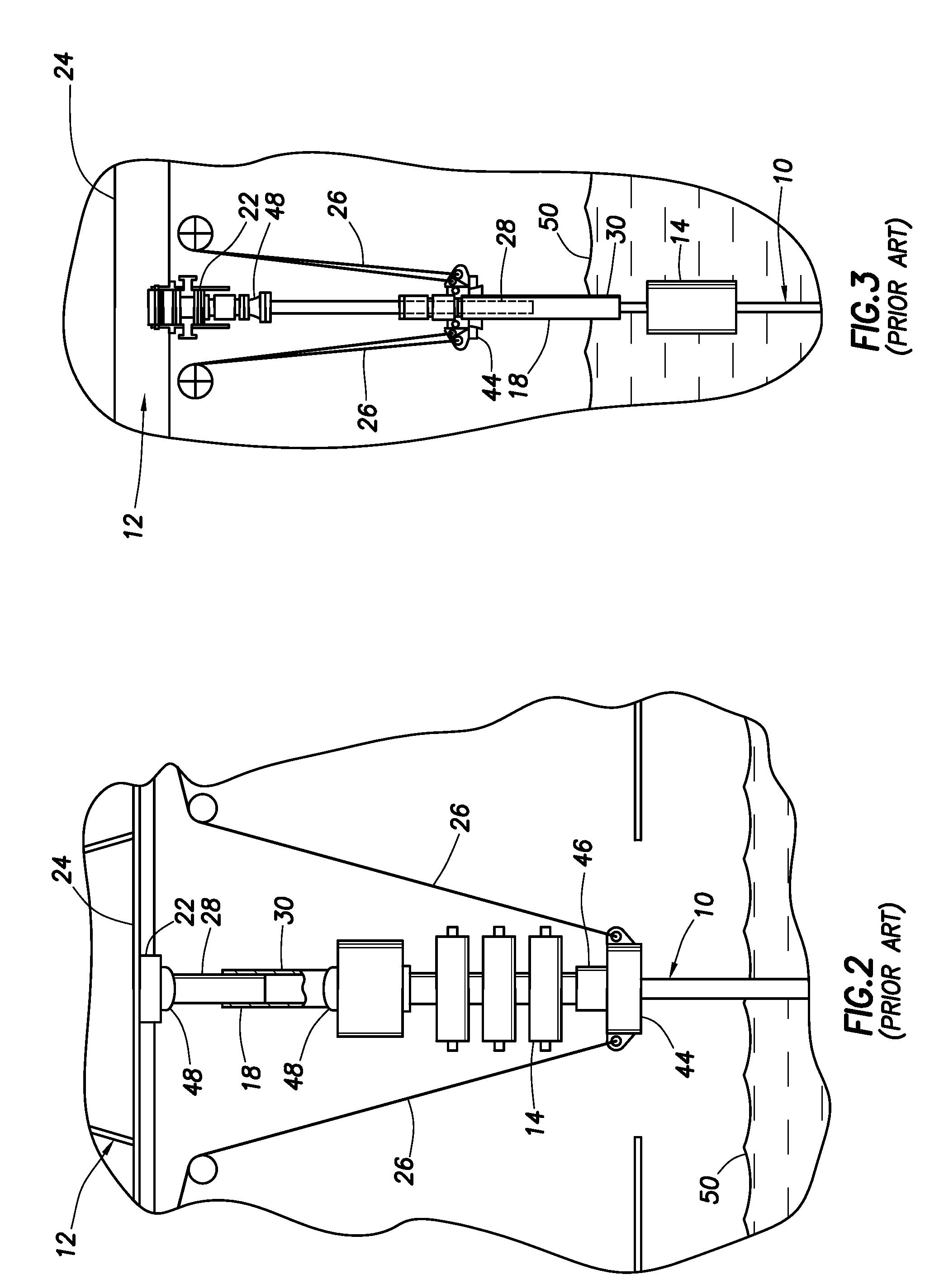
Thus, the FIG. 2 example is unsuited for use in environments in which substantial heave is encountered.
In addition, the FIG. 2 example is unsuited for use with a pressurized riser assembly 10 since the diverter 22 vents the upper end of the riser assembly to atmosphere and no annular seal (such as a rotating control device) is provided.
However, this configuration introduces additional problems associated with access to the submerged BOP stack 14, extended length control and circulation lines, etc.
In addition, the FIG. 3 example is still unsuited for use with a pressurized riser assembly 10.
It will be appreciated that such lateral displacement is very undesirable (especially when the drill pipe 56 is not present) and significantly limits the allowable heave for the FIG. 4 example.

Method used


Image

  • Multipart Sliding Joint For Floating Rig
  • Multipart Sliding Joint For Floating Rig
  • Multipart Sliding Joint For Floating Rig

Examples


Embodiment Construction

[0033]It is to be understood that the various embodiments of the present invention described herein may be utilized in various orientations, such as inclined, inverted, horizontal, vertical, etc., and in various configurations, without departing from the principles of the present invention. The embodiments are described merely as examples of useful applications of the principles of the invention, which is not limited to any specific details of these embodiments.

[0034]In the following description of the representative embodiments of the invention, directional terms, such as “above”, “below”, “upper”, “lower”, etc., are used for convenience in referring to the accompanying drawings. In general, “above”, “upper”, “upward” and similar terms refer to a direction away from the earth's center, and “below”, “lower”, “downward” and similar terms refer to a direction toward the earth's center.

[0035]Representatively and schematically illustrated in FIG. 5 is a system 60 for interconnecting a f...


PUM


Abstract

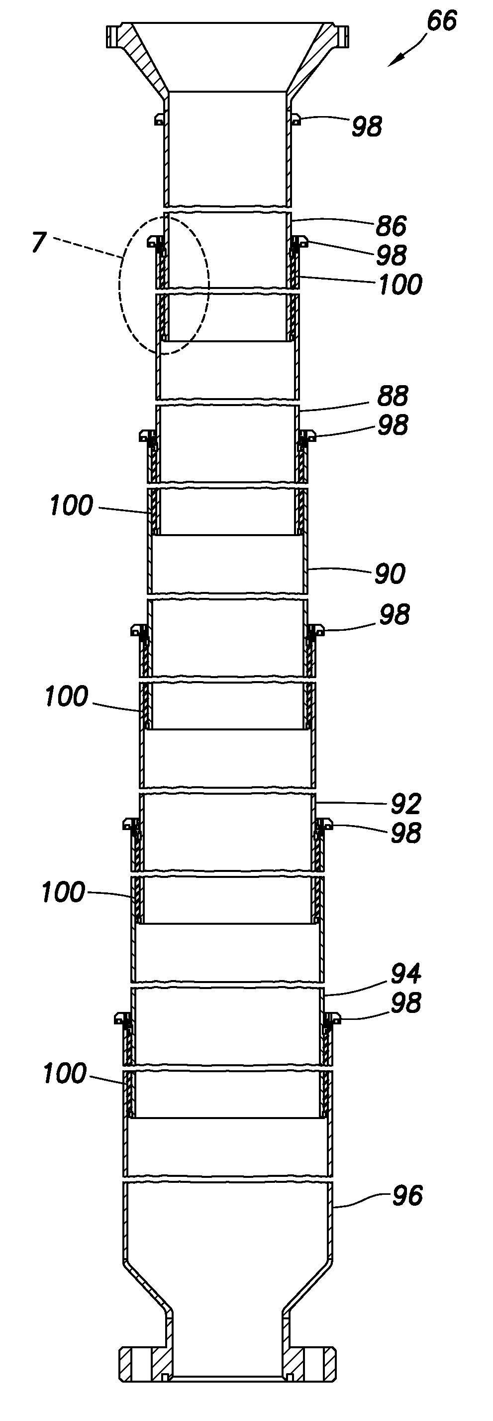
A system for interconnecting a floating rig and a riser assembly includes a rotating control device permitting pressurization of the riser assembly; and a sliding joint connected to the rotating control device, the sliding joint being longitudinally extendable and compressible while the riser assembly is pressurized. Another system includes a sliding joint including more than two telescoping sleeves, and the sliding joint being longitudinally extendable and compressible while the riser assembly is pressurized at the surface. An apparatus includes a sliding joint with multiple sets of telescoping sleeves, each set including at least two of the sleeves. Another apparatus includes a sliding joint with multiple radially overlapping seal assemblies.

Description

BACKGROUND[0001]The present invention relates generally to equipment utilized and operations performed in conjunction with a subterranean well and, in an embodiment described herein, more particularly provides a multipart sliding joint for use with a floating rig.[0002]Slip joints have been widely used for interconnecting a riser assembly to a floating rig. Floating rigs may be drill ships, semi-submersibles, floating drilling or production platforms, etc., and may be dynamically positioned, tethered, or otherwise maintained in position. A slip joint basically allows a riser assembly to alternately lengthen and shorten as a floating rig moves up and down (heaves) in response to wave action.[0003]Recent developments in drilling and completion technology (such as managed pressure drilling) benefit from use of an internally pressurized riser assembly. Unfortunately, typical slip joints and methods of interconnecting riser assemblies to floating rigs are unsuited for use with pressurize...

Claims


Application Information

Patent Timeline
Patent Type & Authority Applications(United States)
IPC IPC(8): E21B17/07
CPCE21B17/07E21B17/085E21B21/08E21B17/08
Inventor LEUCHTENBERG, CHRISTIAN
Owner HALLIBURTON ENERGY SERVICES INC
Learn More