Imaging apparatus and method for controlling the same

Inactive Publication Date: 2008-10-23
CANON KK
View PDF6 Cites 8 Cited by
  • Summary
  • Abstract
  • Description
  • Claims
  • Application Information

AI Technical Summary

Benefits of technology

[0013]Exemplary embodiments of the present invention are directed to an imaging apparatus that includes a m

Problems solved by technology

However, if the focal-plane shutter discussed in Japanese Utility Model Publication No. 6-26895 is incorporated in an imaging apparatus having an EVF discussed in Japanese Patent Application Laid-Open No. 2001-215555 or Japanese Patent Application Laid-Open No. 2001-23220, the following problems arise.
Therefore, not only electric power consumption increases but also the departure timing of the electromagnet changes due to heat generation in the electromagnet.
Thus, the accuracy in exposure control deteriorates.
Furthermore, for a similar reason, the accurac

Method used


Image

  • Imaging apparatus and method for controlling the same
  • Imaging apparatus and method for controlling the same
  • Imaging apparatus and method for controlling the same

Examples


first exemplary embodiment

[0049]Constituent components described in an exemplary embodiment have dimensions, shapes, and mutual positional relationships, which can be appropriately modified according to an apparatus to which the present invention is applied or according to other conditions. Therefore, the present invention is not limited to each example.

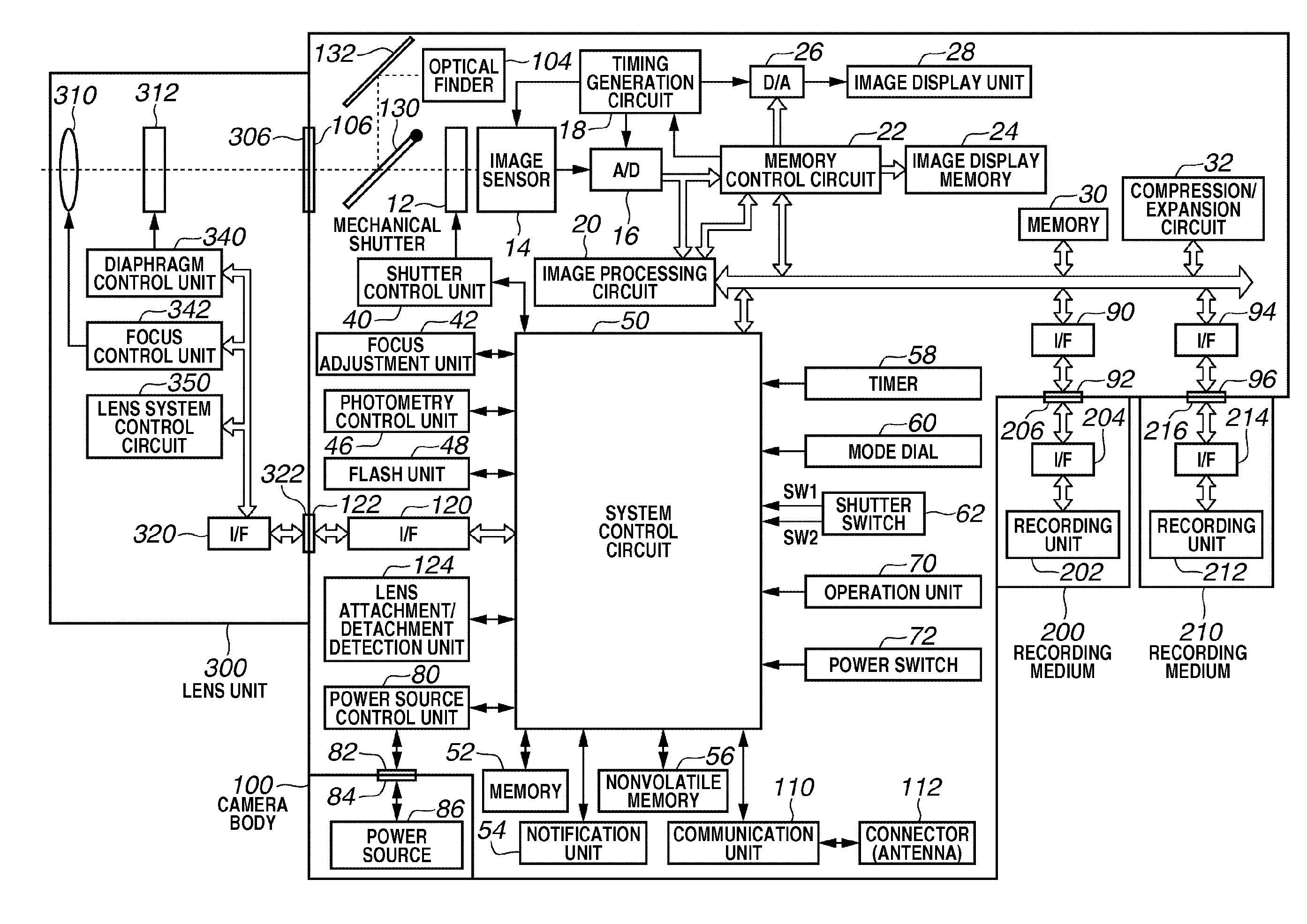
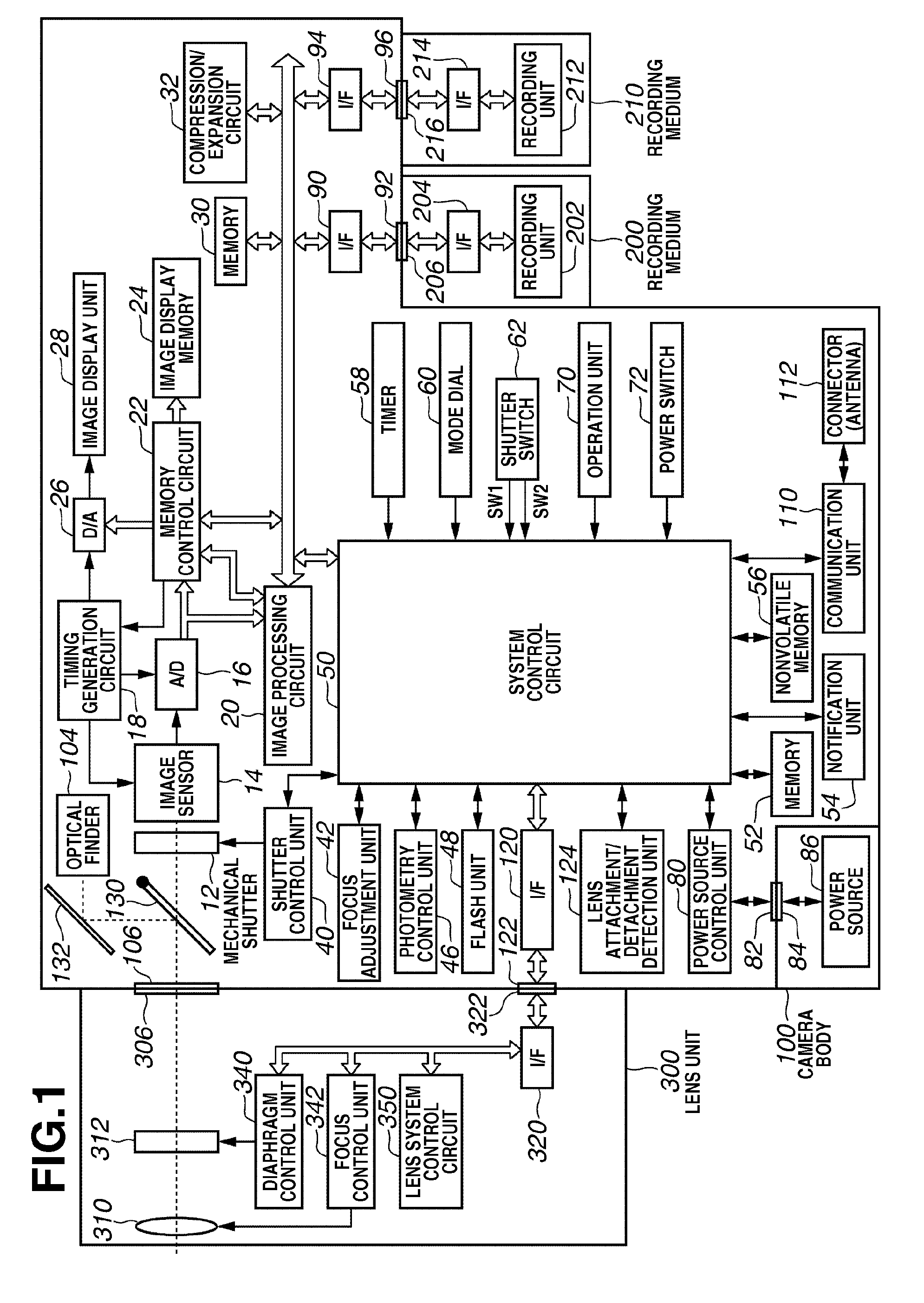
[0050]FIG. 1 is a block diagram illustrating an example imaging system according to an exemplary embodiment of the present invention, which includes a camera body 100 and a lens unit 300. The lens unit 300 is detachable from the camera body 100. The lens unit 300 is an interchangeable lens unit that includes a focal length changing mechanism and a focusing mechanism (not illustrated).

[0051]The lens unit 300 includes an optical lens 310, a diaphragm 312, and a lens mount 306. The lens mount 306 can engage with a camera mount 106 of the camera body 100. For example, both the lens mount 306 and the camera mount 106 are flange type. The lens unit 300 can be attac...

second exemplary embodiment

[0191]FIG. 17 is a flowchart illustrating an example control operation for the mechanical shutter 12 in the ordinary shooting mode according to a second exemplary embodiment of the present invention. In this exemplary embodiment, constituent components similar to those described in the first exemplary embodiment are denoted by the same reference numerals.

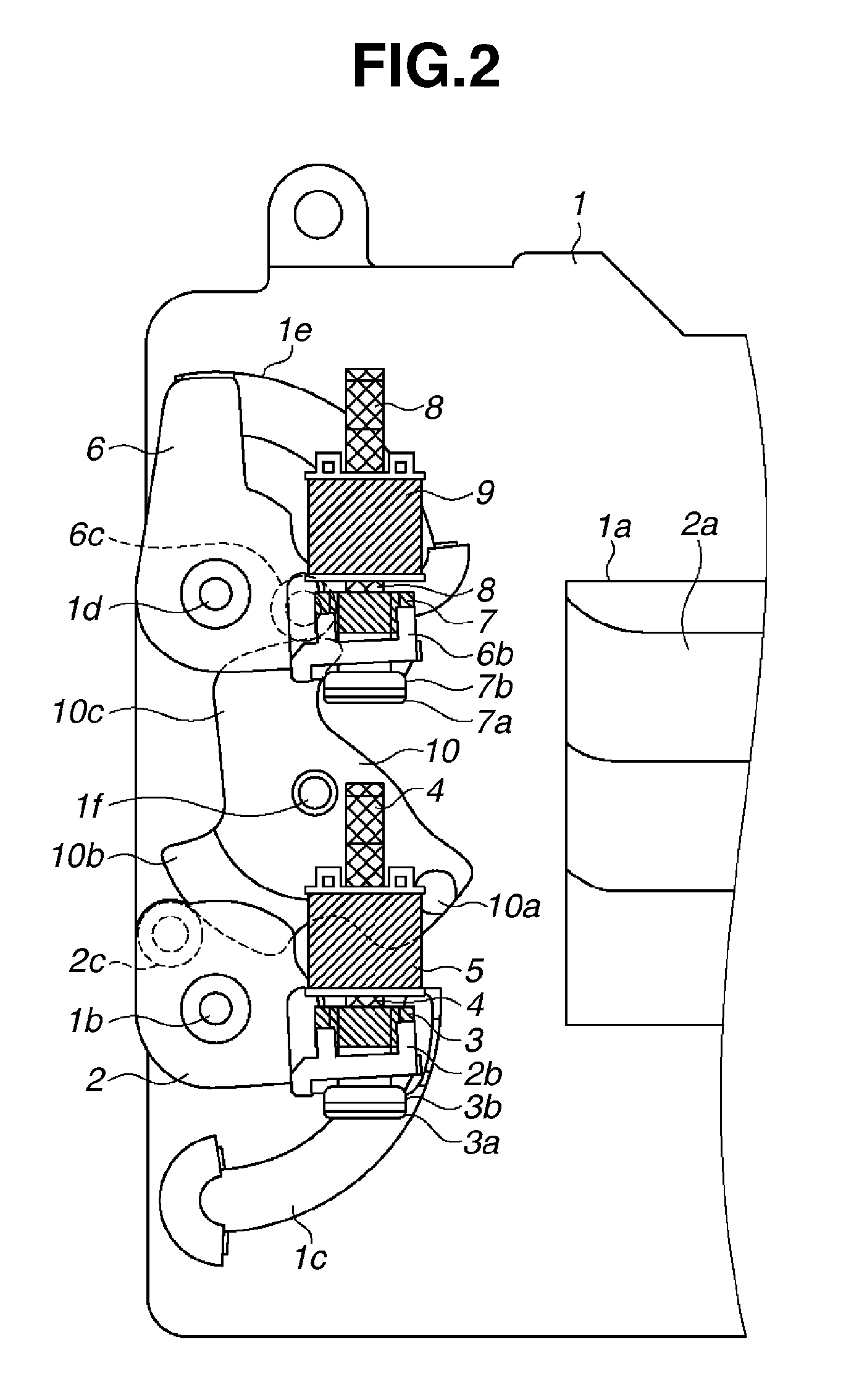
[0192]In step S111, the system control circuit 50 sets the mechanical shutter 12 into the overcharge state illustrated in FIG. 2 before a user performs an ordinary shooting mode (i.e., fully presses the shutter switch 62 to turn on the switch SW2).

[0193]In step S112, the system control circuit 50 determines whether the shutter switch 62 is pressed (i.e., whether the switch SW2 is turned on). If a user does not press the switch SW2 (NO in step S112), the system control circuit 50 repeats the determination processing with respect to the shutter switch 62 in step S112. If the switch SW2 is turned on (YES in step S112), the control flow...


PUM


Abstract

An imaging apparatus includes an image sensor configured to capture an image of an object, a mechanical shutter including a second curtain and a second-curtain holding mechanism configured to electromagnetically hold the second curtain at an initial position prior to a travel, a first temperature sensor disposed within a predetermined range from the second-curtain holding mechanism, a second temperature sensor disposed outside the predetermined range from the second-curtain holding mechanism, a determination unit configured to determine an exposure time for the image sensor according to a brightness of the object, an adjustment unit configured to adjust the exposure time if a temperature difference between temperatures detected by the first and second temperature sensors is greater than a predetermined threshold, and an exposure control unit configured to perform exposure control for the image sensor based on the exposure time adjusted by the adjustment unit if the temperature difference is greater than the predetermined threshold.

Description

BACKGROUND OF THE INVENTION[0001]1. Field of the Invention[0002]The present invention relates to an imaging apparatus and a method for control the imaging apparatus, and more particularly relates to an imaging apparatus including a mechanical shutter and a control method for the same.[0003]2. Description of the Related Art[0004]As discussed in Japanese Utility Model Publication No. 6-26895, a direct-holding type focal-plane shutter holds first and second curtains of a shutter in a charge state by energizing electromagnets corresponding to the first and second curtains and controls an exposure time by successively stopping energizing respective electromagnets.[0005]As discussed in Japanese Patent Application Laid-Open No. 2005-283897, there is a direct-holding type focal-plane shutter that can reduce electric power consumption by changing a power voltage during energization control for the electromagnets.[0006]Furthermore, as discussed in Japanese Patent Application Laid-Open No. 58-...

Claims


Application Information

Patent Timeline
IPC IPC(8): G03B7/00G03B7/093G03B9/36H04N5/235H04N5/335H04N5/353
CPCG03B7/00H04N5/2254H04N5/2353H04N23/55H04N23/651H04N23/634H04N23/631H04N23/73G03B7/22
Inventor KAWASHIMA, TORU
Owner CANON KK
Why Eureka
Try Eureka