Balancing mass system of photoetching machine

A technology of balancing mass and balancing mass, which is applied in the direction of microlithography exposure equipment, photolithography exposure device, etc., can solve problems such as inability to perform lubrication, blockage of orifice, and influence on control accuracy, so as to improve motion and Exposure accuracy, the effect of increasing damping

Active Publication Date: 2012-12-05
SHANGHAI MICRO ELECTRONICS EQUIP (GRP) CO LTD
View PDF10 Cites 9 Cited by
  • Summary
  • Abstract
  • Description
  • Claims
  • Application Information

AI Technical Summary

Problems solved by technology

However, this structure has its disadvantages. When the micro-motion table moves at a high speed, the balance mass moves in the opposite direction; However, the tilting moment generated by the offset of the center of gravity of the balance mass block directly presses the air bearing; on the one hand, the thickness of the air film changes at any time, causing instability in stiffness and affecting control accuracy. , the overturning moment generated by the offset of the center of gravity of the balance mass block is very large, and the pressure on the air film is correspondingly large, which may make the thickness of the air film too small, causing the orifice to be blocked and unable to play a lubrication role; while the balance mass block The vibration will also be directly transmitted to the foundation frame through the air flotation, the damping of the air flotation is very low, and the effect on vibration attenuation is very limited
The vibration of the basic frame will cause the vibration of the micro-motion table, which directly affects the exposure accuracy

Method used


Image

  • Balancing mass system of photoetching machine
  • Balancing mass system of photoetching machine
  • Balancing mass system of photoetching machine

Examples


Embodiment 1

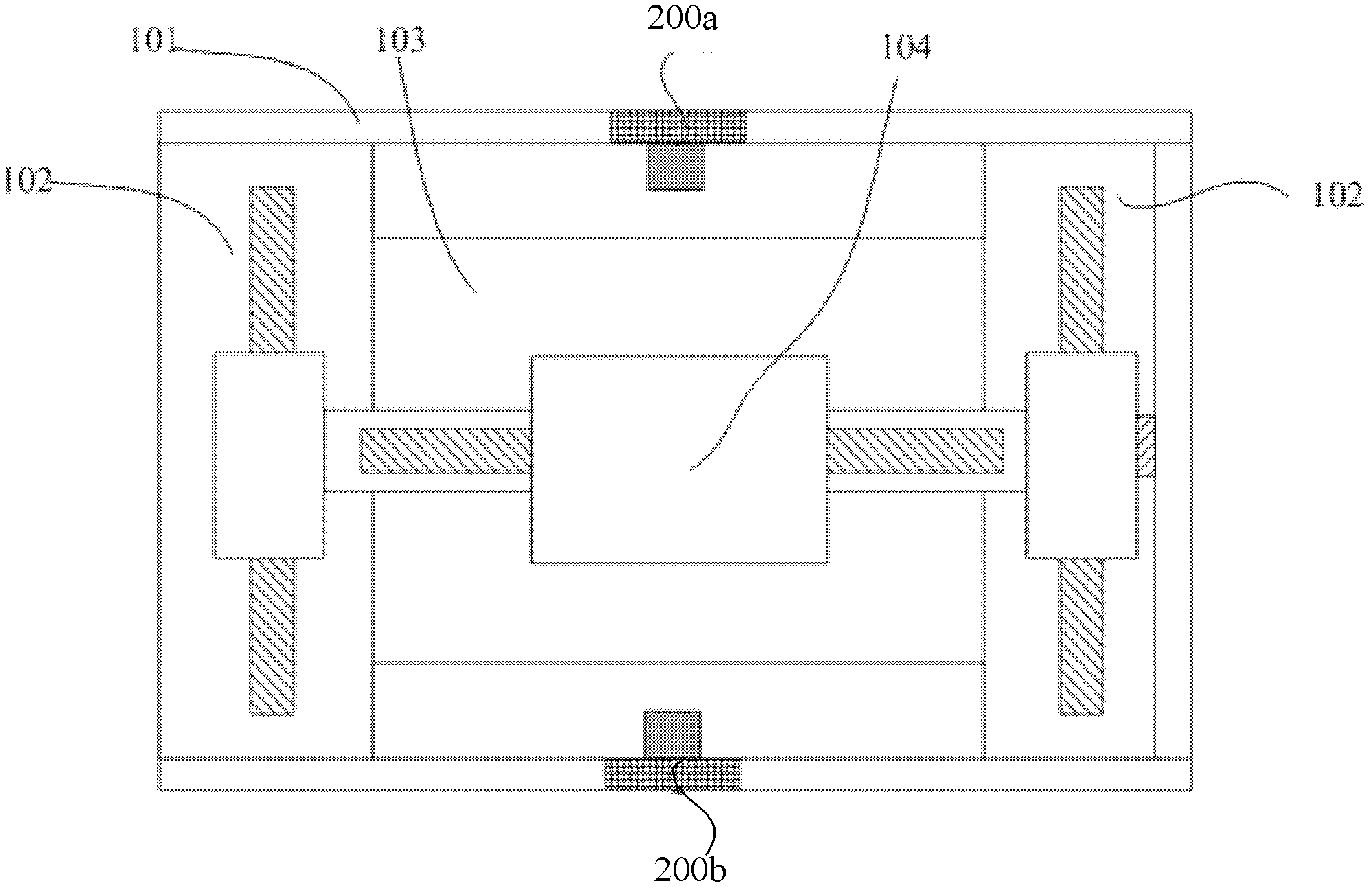
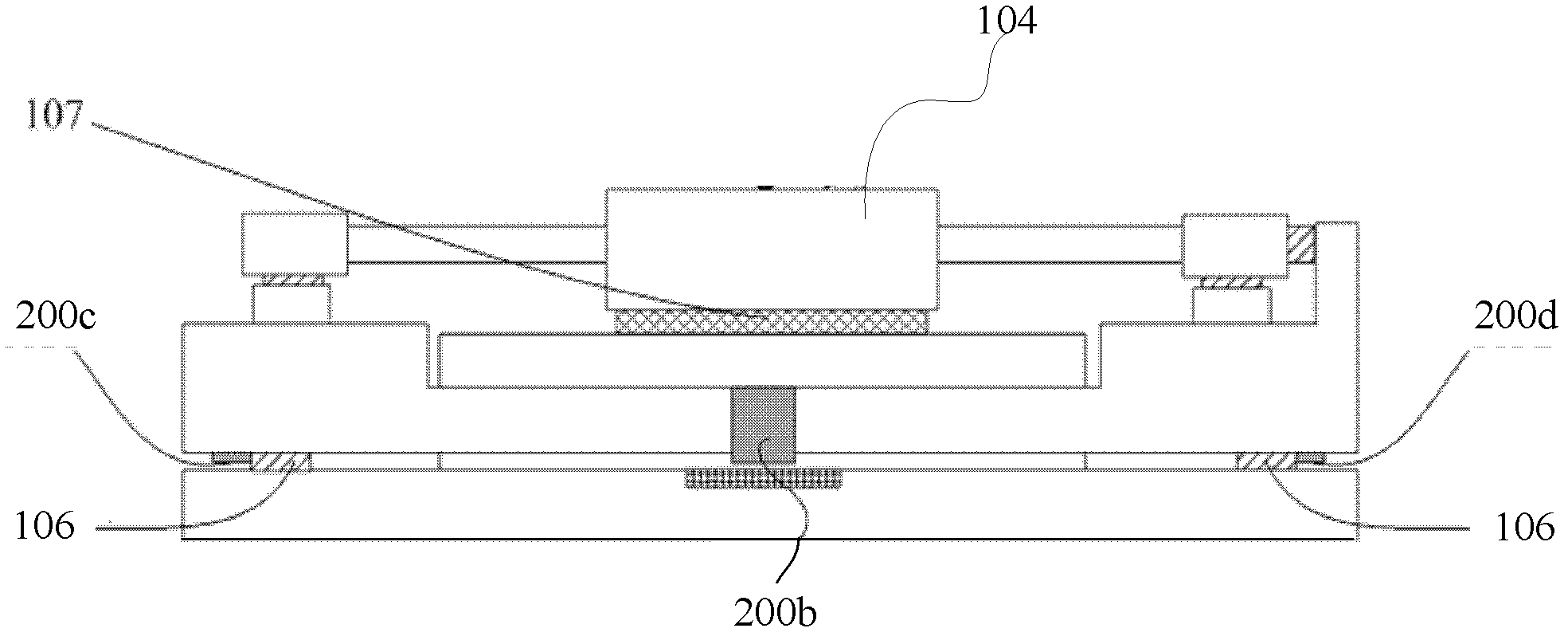
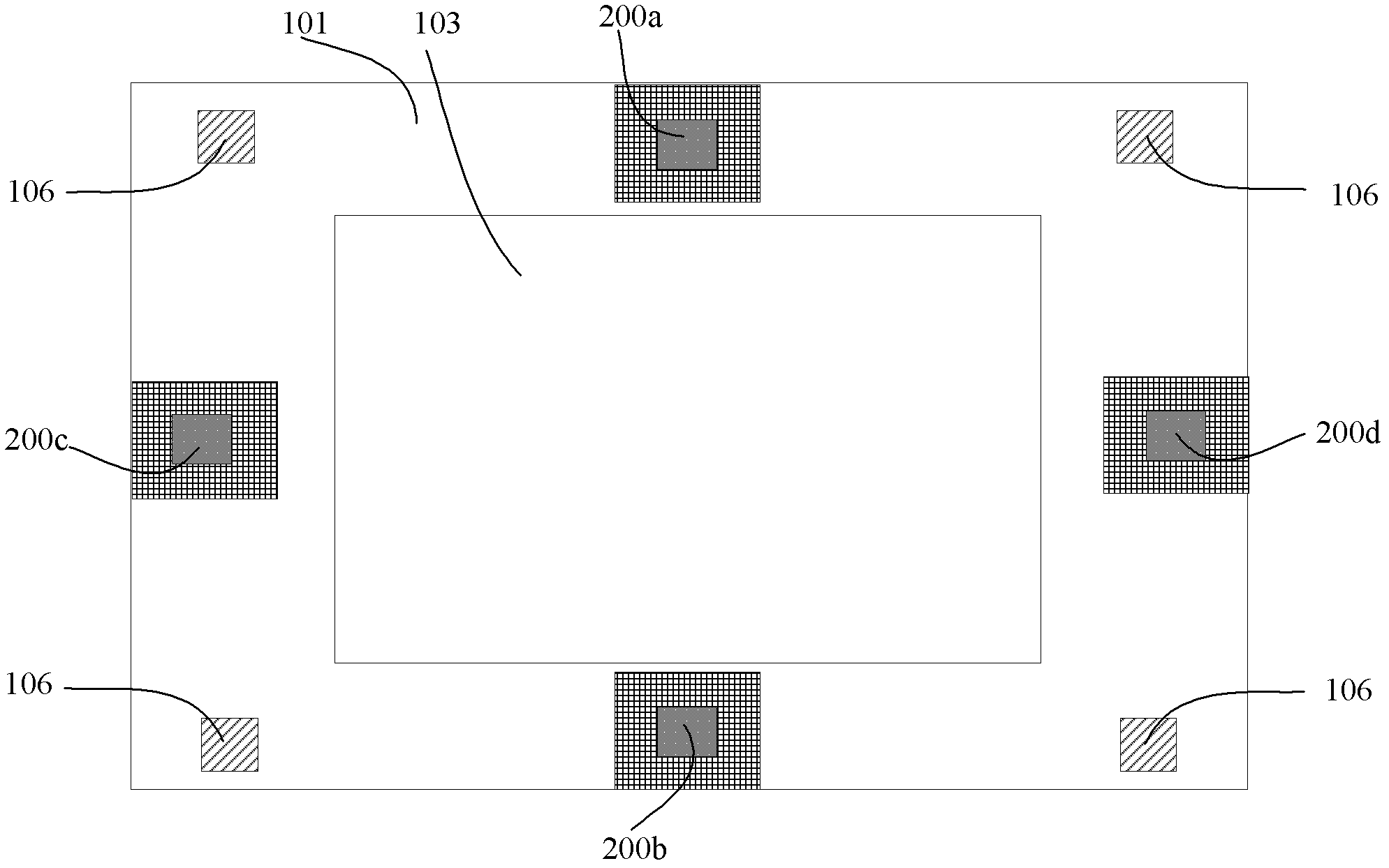
[0042] Please refer to Figure 1 to Figure 4 ,among them, figure 1 Is a top view of the balance mass system of a lithography machine provided by the first embodiment of the present invention, figure 2 This is a front view of the balance mass system of a lithography machine provided by the first embodiment of the present invention, image 3 It is a schematic diagram of the installation position of the reaction moment buffer mechanism provided by the first embodiment of the present invention, Figure 4 It is a schematic diagram of the structure of the reaction moment buffer mechanism provided by the first embodiment of the present invention, such as Figure 1 to Figure 4 As shown, the lithography machine quality balance system provided by the first embodiment of the present invention includes:

[0043] Basic frame 101;

[0044] The marble platform 103 is fixed on the base frame 101;

[0045] The micro-movement platform 104 is supported on the marble platform 103 by the first vertical a...

Embodiment 2

[0061] Please refer to Figure 5 to Figure 6 ,among them, Figure 5 Is a schematic diagram of the installation position of the reaction moment buffer mechanism provided by the second embodiment of the present invention, Image 6 This is a schematic diagram of the structure of the reaction moment buffer mechanism provided by the second embodiment of the present invention, such as Figure 5 to Figure 6 Shown and combined with reference figure 1 and figure 2 , The second embodiment of the present invention provides a lithography machine balance quality system including:

[0062] Basic frame 101;

[0063] The marble platform 103 is fixed on the base frame 101;

[0064] The micro-movement platform 104 is supported on the marble platform 103 by the first vertical air floating cushion 107, and moves relative to the marble platform 103 along the X direction and the Y direction;

[0065] The balance mass 102 is connected to the base frame 101 through a second vertical air cushion 106, the se...


PUM

PropertyMeasurementUnit
distanceaaaaaaaaaa

Abstract

The invention discloses a balancing mass system of a photoetching machine. The system comprises a foundation frame, a marble platform, a micro-motion platform, a balancing mass and a countertorque buffering mechanism; the marble platform is fixed on the foundation frame; the micro-motion platform is supported on the marble platform through a vertical air floating cushion, and moves relative to the marble platform along an X direction and a Y direction; the balancing mass is connected with the foundation frame through another vertical air floating cushion, the vertical air floating cushion is fixed on the foundation frame, and the movement condition of the balancing mass is opposite to that of the micro-motion platform; the countertorque buffering mechanism is connected with the foundation frame and the balancing mass, and is used for eliminating torque generated due to the fact that the gravity center of the balancing mass shifts when the balancing mass moves, and vibration which is transmitted to the foundation frame by the balancing mass is attenuated. Accordingly, properties of the system of the photoetching machine can be improved.

Description

Technical field [0001] The invention relates to the technical field of semiconductor equipment, in particular to a lithography machine balance quality system. Background technique [0002] A photolithography apparatus is a device that exposes and image mask patterns onto a silicon wafer, and is mainly used for the manufacture of integrated circuits (IC) or other micro devices. The lithography device is roughly divided into two categories: one is a stepper lithography device. The mask pattern is exposed and imaged on an exposure area of ​​the silicon wafer at a time, and then the silicon wafer is moved relative to the mask to move the next exposure area to the mask. Under the mold pattern and the projection objective lens, the mask pattern is once again exposed to another exposure area of ​​the silicon wafer, and this process is repeated until all exposed areas on the silicon wafer have the image of the mask pattern; the other type is step-scanning light In the engraving device, ...

Claims


Application Information

Patent Timeline
Patent Type & Authority Applications(China)
IPC IPC(8): G03F7/20
Inventor 夏海陈庆生
Owner SHANGHAI MICRO ELECTRONICS EQUIP (GRP) CO LTD
Why Eureka
Try Eureka