Method of manufacturing a connecting rod assembly for an internal combustion engine

a technology of connecting rods and internal combustion engines, which is applied in the direction of connecting rod bearings, manufacturing tools, machines/engines, etc., can solve the problems of engine damage, premature bushing failure, and reduce the optimum efficiency at this pivot point, so as to reduce the likelihood of deformation of the bushing, reduce the moment force, and eliminate the effect of moment forces

Inactive Publication Date: 2009-04-14
MAHLE TECH
View PDF43 Cites 12 Cited by
  • Summary
  • Abstract
  • Description
  • Claims
  • Application Information

AI Technical Summary

Benefits of technology

[0015]Accordingly, one advantage of the present invention is that it essentially eliminates the moment forces generated when installing a bushing into a pin bore of a stepped small end of a connecting rod assembly, thereby reducing the likelihood of deforming the bushing and creating an irregular contact area between the bushing and connecting rod assembly pin bore.
[0016]Another advantage of the present invention is that it reduces the moment forces generated when defining a contact surface within the pin bore of a stepped small end of a connecting rod assembly that receives a piston pin, thereby reducing the likelihood of deforming the distal ends of the contact surface and creating an irregular pivot point between the contact surface and the piston pin.
[0017]Still another advantage of the present invention is that it streamlines the manufacture of a connecting rod assembly by reducing the need for inspecting and correcting irregularities caused by moment forces generated during installation of a bushing.
[0018]Still another advantage of the present invention is that it streamlines the manufacture of a connecting rod assembly and connecting rod assembly by reducing the need for inspecting and correcting irregularities caused by moment forces generated during machining to define a contact surface within the small end that engages a piston pin.

Problems solved by technology

This can result in misalignment between the bushing and pin bore or deformation of the bushing, creating irregular contact between the bushing and the pin bore, which may lead to premature bushing failure.
Additionally, this misalignment can translate to an irregular bushing surface that contacts the piston pin, which may promote scuffing and lead to engine damage.
This shift has a tendency to create a concave lower surface, which reduces optimum efficiency at this pivot point.
The creation of such a non-uniform contact surface may lead to premature failure of the pivot point between the contact surface and the piston pin, which can lead to engine damage.
The irregularities caused by the moment forces associated with installing a bushing in the pin bore of stepped small end of a connecting rod assembly as well as those associated with machining the contact surface in the pin bore are detrimental to the efficiency and cost-effectiveness of manufacturing connecting rod assemblies.
Notably, these irregularities impose additional steps in the manufacturing process to inspect connecting rod assemblies and correct the irregularities where appropriate, which increases costs associated with additional labor, additional machining and lost manufacturing.
Further, these irregularities can cause an out-of-tolerance condition, rendering the entire connecting rod assembly unusable.

Method used


Image

  • Method of manufacturing a connecting rod assembly for an internal combustion engine
  • Method of manufacturing a connecting rod assembly for an internal combustion engine
  • Method of manufacturing a connecting rod assembly for an internal combustion engine

Examples


Embodiment Construction

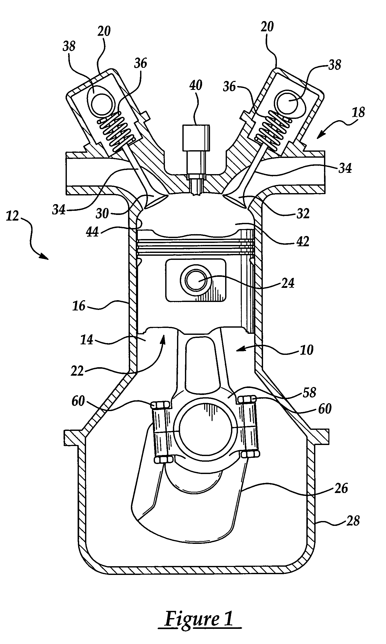
[0028]A connecting rod assembly manufactured pursuant to the method of the present invention is generally indicated at 10 throughout the figures, where like numbers are used to designate like structures throughout the drawings. As shown in FIG. 1, the present invention is particularly adapted for use in an internal combustion engine, generally indicated at 12. In this case, the assembly 10 of the present invention is illustrated in connection with a single cylinder 14 of an internal combustion engine 12 having a dual-overhead cam arrangement. Those having ordinary skill in the art will appreciate that the engine 12 is but one of the many internal combustion engines with which the present invention may be employed. By way of example, the present invention may be employed to manufacture a connecting rod assembly used in a two-stroke or four-stroke engine. The cylinders may be arranged in an in-line, v-shaped, or flat manner or in any other manner commonly known in the art. The present...


PUM

PropertyMeasurementUnit
widthaaaaaaaaaa
thermal expansionaaaaaaaaaa
diameteraaaaaaaaaa

Abstract

The present invention relates to a method of manufacturing a connecting rod assembly having a stepped small end. The method includes defining a small end of a connecting rod assembly having a terminal end and defining a pin bore extending therethrough. A pair of channels are formed on opposite sides of the small end, perpendicular to the pin bore and a bushing is subsequently installed into the pin bore. Where a connecting rod assembly does not include a bushing the method includes defining a small end having a pin bore and forming pair of channels on opposite sides of the small end. A contact surface is then defined within the pin bore to engage a piston pin and the small end is machined to provide a stepped configuration. The connecting rod assembly is then machined to reduce the width of the small end to provide a stepped configuration.

Description

BACKGROUND OF THE INVENTION[0001]1. Field of the Invention[0002]The present invention relates, generally, to a connecting rod assembly and, more specifically, to a method of manufacturing a connecting rod assembly for an internal combustion engine.[0003]2. Description of the Related Art[0004]Internal combustion engines known in the related art may generally include, among other basic components, an engine block having one or more cylinders, cylinder heads associated with the engine block, pistons supported for reciprocal movement in each cylinder, and connecting rod assemblies to transfer the movement of the pistons to the crankshaft. The piston generally includes a bore that corresponds to a similar pin bore at one end of the connecting rod assembly. A pin is placed through the corresponding bores to attach the piston to the connecting rod assembly. The end of a connecting rod assembly having the pin bore is commonly referred to as the “small end.” The other end of a connecting rod...

Claims


Application Information

Patent Timeline
Patent Type & Authority Patents(United States)
IPC IPC(8): B21D53/84B23D13/04B23P11/02F16C7/00F16C7/02F16J1/14
CPCB22F5/00B23P15/00F16C7/023F16C9/04Y10T29/49995B22F2998/10B23P2700/04B22F2998/00Y10T29/49945Y10T29/49288Y10T74/2162Y10T29/49291Y10T29/49696Y10T29/49865Y10T74/2142B22F5/10B22F3/02B22F3/10F16C2360/22F16C33/14F16J1/16F16C17/02
Inventor MCEWAN, ALAN STEPHEN
Owner MAHLE TECH
Why Eureka
Try Eureka